Capacitor and Capacitance:
.jpg) | |
| Type | Passive |
|---|---|
| Invented | Ewald Georg von Kleist |
| Electronic symbol | |
 | |
The effect of a capacitor is known as capacitance. While some capacitance exists between any two electrical conductors in proximity in a circuit, a capacitor is a component designed to add capacitance to a circuit. The capacitor was originally known as a condenser or condensator.[1] This name and its cognates are still widely used in many languages, but rarely in English, one notable exception being condenser microphones, also called capacitor microphones.
The physical form and construction of practical capacitors vary widely and many types of capacitor are in common use. Most capacitors contain at least two electrical conductors often in the form of metallic plates or surfaces separated by a dielectric medium. A conductor may be a foil, thin film, sintered bead of metal, or an electrolyte. The nonconducting dielectric acts to increase the capacitor's charge capacity. Materials commonly used as dielectrics include glass, ceramic, plastic film, paper, mica, air, and oxide layers. Capacitors are widely used as parts of electrical circuits in many common electrical devices. Unlike a resistor, an ideal capacitor does not dissipate energy, although real-life capacitors do dissipate a small amount (see Non-ideal behavior). When an electric potential difference (a voltage) is applied across the terminals of a capacitor, for example when a capacitor is connected across a battery, an electric field develops across the dielectric, causing a net positive charge to collect on one plate and net negative charge to collect on the other plate. No current actually flows through the dielectric. However, there is a flow of charge through the source circuit. If the condition is maintained sufficiently long, the current through the source circuit ceases. If a time-varying voltage is applied across the leads of the capacitor, the source experiences an ongoing current due to the charging and discharging cycles of the capacitor.
The earliest forms of capacitors were created in the 1740s, when European experimenters discovered that electric charge could be stored in water-filled glass jars that came to be known as Leyden jars. Today, capacitors are widely used in electronic circuits for blocking direct current while allowing alternating current to pass. In analog filter networks, they smooth the output of power supplies. In resonant circuits they tune radios to particular frequencies. In electric power transmission systems, they stabilize voltage and power flow.[2] The property of energy storage in capacitors was exploited as dynamic memory in early digital computers,[3] and still is in modern DRAM.
HistoryEdit

In October 1745, Ewald Georg von Kleist of Pomerania, Germany, found that charge could be stored by connecting a high-voltage electrostatic generator by a wire to a volume of water in a hand-held glass jar.[4] Von Kleist's hand and the water acted as conductors, and the jar as a dielectric (although details of the mechanism were incorrectly identified at the time). Von Kleist found that touching the wire resulted in a powerful spark, much more painful than that obtained from an electrostatic machine. The following year, the Dutch physicist Pieter van Musschenbroek invented a similar capacitor, which was named the Leyden jar, after the University of Leiden where he worked.[5] He also was impressed by the power of the shock he received, writing, "I would not take a second shock for the kingdom of France."[6]
Daniel Gralath was the first to combine several jars in parallel to increase the charge storage capacity.[7] Benjamin Franklin investigated the Leyden jar and came to the conclusion that the charge was stored on the glass, not in the water as others had assumed. He also adopted the term "battery",[8][9] (denoting the increase of power with a row of similar units as in a battery of cannon), subsequently applied to clusters of electrochemical cells.[10] Leyden jars were later made by coating the inside and outside of jars with metal foil, leaving a space at the mouth to prevent arcing between the foils.[citation needed] The earliest unit of capacitance was the jar, equivalent to about 1.11 nanofarads.[11]
Leyden jars or more powerful devices employing flat glass plates alternating with foil conductors were used exclusively up until about 1900, when the invention of wireless (radio) created a demand for standard capacitors, and the steady move to higher frequencies required capacitors with lower inductance. More compact construction methods began to be used, such as a flexible dielectric sheet (like oiled paper) sandwiched between sheets of metal foil, rolled or folded into a small package.

Early capacitors were known as condensers, a term that is still occasionally used today, particularly in high power applications, such as automotive systems. The term was first used for this purpose by Alessandro Volta in 1782, with reference to the device's ability to store a higher density of electric charge than was possible with an isolated conductor.[12][1] The term became deprecated because of the ambiguous meaning of steam condenser, with capacitor becoming the recommended term from 1926.[13]
Since the beginning of the study of electricity non conductive materials like glass, porcelain, paper and mica have been used as insulators. These materials some decades later were also well-suited for further use as the dielectric for the first capacitors. Paper capacitors made by sandwiching a strip of impregnated paper between strips of metal, and rolling the result into a cylinder were commonly used in the late 19th century; their manufacture started in 1876,[14] and they were used from the early 20th century as decoupling capacitors in telecommunications (telephony).
Porcelain was used in the first ceramic capacitors. In the early years of Marconi's wireless transmitting apparatus porcelain capacitors were used for high voltage and high frequency application in the transmitters. On the receiver side smaller mica capacitors were used for resonant circuits. Mica dielectric capacitors were invented in 1909 by William Dubilier. Prior to World War II, mica was the most common dielectric for capacitors in the United States.[14]
Charles Pollak (born Karol Pollak), the inventor of the first electrolytic capacitors, found out that the oxide layer on an aluminum anode remained stable in a neutral or alkaline electrolyte, even when the power was switched off. In 1896 he was granted U.S. Patent No. 672,913 for an "Electric liquid capacitor with aluminum electrodes". Solid electrolyte tantalum capacitors were invented by Bell Laboratories in the early 1950s as a miniaturized and more reliable low-voltage support capacitor to complement their newly invented transistor.
With the development of plastic materials by organic chemists during the Second World War, the capacitor industry began to replace paper with thinner polymer films. One very early development in film capacitors was described in British Patent 587,953 in 1944.[14]
Electric double-layer capacitors (now supercapacitors) were invented in 1957 when H. Becker developed a "Low voltage electrolytic capacitor with porous carbon electrodes".[14][15][16] He believed that the energy was stored as a charge in the carbon pores used in his capacitor as in the pores of the etched foils of electrolytic capacitors. Because the double layer mechanism was not known by him at the time, he wrote in the patent: "It is not known exactly what is taking place in the component if it is used for energy storage, but it leads to an extremely high capacity."
The metal–oxide–semiconductor capacitor (MOS capacitor) originates from the metal–oxide–semiconductor field-effect transistor (MOSFET) structure, where the MOS capacitor is flanked by two doped regions.[17] The MOSFET structure was invented by Mohamed M. Atalla and Dawon Kahng at Bell Labs in 1959.[18] The MOS capacitor was later widely adopted as a storage capacitor in memory chips, and as the basic building block of the charge-coupled device (CCD) in image sensor technology.[19] In dynamic random-access memory (DRAM), each memory cell typically consists of a MOSFET and MOS capacitor.[20]
Theory of operationEdit
OverviewEdit


A capacitor consists of two conductors separated by a non-conductive region.[21] The non-conductive region can either be a vacuum or an electrical insulator material known as a dielectric. Examples of dielectric media are glass, air, paper, plastic, ceramic, and even a semiconductor depletion region chemically identical to the conductors. From Coulomb's law a charge on one conductor will exert a force on the charge carriers within the other conductor, attracting opposite polarity charge and repelling like polarity charges, thus an opposite polarity charge will be induced on the surface of the other conductor. The conductors thus hold equal and opposite charges on their facing surfaces,[22] and the dielectric develops an electric field.
An ideal capacitor is characterized by a constant capacitance C, in farads in the SI system of units, defined as the ratio of the positive or negative charge Q on each conductor to the voltage V between them:[21]

A capacitance of one farad (F) means that one coulomb of charge on each conductor causes a voltage of one volt across the device.[23] Because the conductors (or plates) are close together, the opposite charges on the conductors attract one another due to their electric fields, allowing the capacitor to store more charge for a given voltage than when the conductors are separated, yielding a larger capacitance.
In practical devices, charge build-up sometimes affects the capacitor mechanically, causing its capacitance to vary. In this case, capacitance is defined in terms of incremental changes:

Hydraulic analogyEdit
In the hydraulic analogy, charge carriers flowing through a wire are analogous to water flowing through a pipe. A capacitor is like a rubber membrane sealed inside a pipe. Water molecules cannot pass through the membrane, but some water can move by stretching the membrane. The analogy clarifies a few aspects of capacitors:
- The current alters the charge on a capacitor, just as the flow of water changes the position of the membrane. More specifically, the effect of an electric current is to increase the charge of one plate of the capacitor, and decrease the charge of the other plate by an equal amount. This is just as when water flow moves the rubber membrane, it increases the amount of water on one side of the membrane, and decreases the amount of water on the other side.
- The more a capacitor is charged, the larger its voltage drop; i.e., the more it "pushes back" against the charging current. This is analogous to the more a membrane is stretched, the more it pushes back on the water.
- Charge can flow "through" a capacitor even though no individual electron can get from one side to the other. This is analogous to water flowing through the pipe even though no water molecule can pass through the rubber membrane. The flow cannot continue in the same direction forever; the capacitor experiences dielectric breakdown, and analogously the membrane will eventually break.
- The capacitance describes how much charge can be stored on one plate of a capacitor for a given "push" (voltage drop). A very stretchy, flexible membrane corresponds to a higher capacitance than a stiff membrane.
- A charged-up capacitor is storing potential energy, analogously to a stretched membrane.
Circuit equivalence at short-time limit and long-time limitEdit
In a circuit, a capacitor can behave differently at different time instants. However, it is usually easy to think about the short-time limit and long-time limit:
- In the long-time limit, after the charging/discharging current has saturated the capacitor, no current would come into (or get out of) either side of the capacitor; Therefore, the long-time equivalence of capacitor is an open circuit.
- In the short-time limit, if the capacitor starts with a certain voltage V, since the voltage drop on the capacitor is known at this instant, we can replace it with an ideal voltage source of voltage V. Specifically, if V=0 (capacitor is uncharged), the short-time equivalence of a capacitor is a short circuit.
Parallel-plate capacitorEdit

The simplest model of a capacitor consists of two thin parallel conductive plates each with an area of 


Since the separation between the plates is uniform over the plate area, the electric field between the plates 


The capacitance is defined as 

Therefore, in a capacitor the highest capacitance is achieved with a high permittivity dielectric material, large plate area, and small separation between the plates.
Since the area 
A parallel plate capacitor can only store a finite amount of energy before dielectric breakdown occurs. The capacitor's dielectric material has a dielectric strength Ud which sets the capacitor's breakdown voltage at V = Vbd = Udd. The maximum energy that the capacitor can store is therefore

The maximum energy is a function of dielectric volume, permittivity, and dielectric strength. Changing the plate area and the separation between the plates while maintaining the same volume causes no change of the maximum amount of energy that the capacitor can store, so long as the distance between plates remains much smaller than both the length and width of the plates. In addition, these equations assume that the electric field is entirely concentrated in the dielectric between the plates. In reality there are fringing fields outside the dielectric, for example between the sides of the capacitor plates, which increase the effective capacitance of the capacitor. This is sometimes called parasitic capacitance. For some simple capacitor geometries this additional capacitance term can be calculated analytically.[24] It becomes negligibly small when the ratios of plate width to separation and length to separation are large.
For unevenly charged plates:
- If one plate is charged with
while the other is charged with
, and if both plates are separated from other materials in the environment, then the inner surface of the first plate will have
, and the inner surface of the second plated will have
charge.[citation needed] Therefore, the voltage
. Note that the outer surface of both plates will have
, but those charges don't affect the voltage between the plates.
- If one plate is charged with
. Therefore, the voltage
. Note that the outer surface of both plates will have zero charge.
Interleaved capacitorEdit

For 

where 
As shown to the figure on the right, the interleaved plates can be seen as parallel plates connected to each other. Every pair of adjacent plates acts as a separate capacitor; the number of pairs is always one less than the number of plates, hence the 
Energy stored in a capacitorEdit
To increase the charge and voltage on a capacitor, work must be done by an external power source to move charge from the negative to the positive plate against the opposing force of the electric field.[25][26] If the voltage on the capacitor is 


where 

If the gap between the capacitor plates 

The last formula above is equal to the energy density per unit volume in the electric field multiplied by the volume of field between the plates, confirming that the energy in the capacitor is stored in its electric field.
Current–voltage relationEdit
The current I(t) through any component in an electric circuit is defined as the rate of flow of a charge Q(t) passing through it, but actual charges – electrons – cannot pass through the dielectric layer of a capacitor. Rather, one electron accumulates on the negative plate for each one that leaves the positive plate, resulting in an electron depletion and consequent positive charge on one electrode that is equal and opposite to the accumulated negative charge on the other. Thus the charge on the electrodes is equal to the integral of the current as well as proportional to the voltage, as discussed above. As with any antiderivative, a constant of integration is added to represent the initial voltage V(t0). This is the integral form of the capacitor equation:[28]

Taking the derivative of this and multiplying by C yields the derivative form:[29]

for C independent of time, voltage and electric charge.
The dual of the capacitor is the inductor, which stores energy in a magnetic field rather than an electric field. Its current-voltage relation is obtained by exchanging current and voltage in the capacitor equations and replacing C with the inductance L.
DC circuitsEdit

A series circuit containing only a resistor, a capacitor, a switch and a constant DC source of voltage V0 is known as a charging circuit.[30] If the capacitor is initially uncharged while the switch is open, and the switch is closed at t=0, it follows from Kirchhoff's voltage law that

Taking the derivative and multiplying by C, gives a first-order differential equation:

At t = 0, the voltage across the capacitor is zero and the voltage across the resistor is V0. The initial current is then I(0) =V0/R. With this assumption, solving the differential equation yields

where τ0 = RC, the time constant of the system. As the capacitor reaches equilibrium with the source voltage, the voltages across the resistor and the current through the entire circuit decay exponentially. In the case of a discharging capacitor, the capacitor's initial voltage (VCi) replaces V0. The equations become

AC circuitsEdit
Impedance, the vector sum of reactance and resistance, describes the phase difference and the ratio of amplitudes between sinusoidally varying voltage and sinusoidally varying current at a given frequency. Fourier analysis allows any signal to be constructed from a spectrum of frequencies, whence the circuit's reaction to the various frequencies may be found. The reactance and impedance of a capacitor are respectively

where j is the imaginary unit and ω is the angular frequency of the sinusoidal signal. The −j phase indicates that the AC voltage V = ZI lags the AC current by 90°: the positive current phase corresponds to increasing voltage as the capacitor charges; zero current corresponds to instantaneous constant voltage, etc.
Impedance decreases with increasing capacitance and increasing frequency.[31] This implies that a higher-frequency signal or a larger capacitor results in a lower voltage amplitude per current amplitude – an AC "short circuit" or AC coupling. Conversely, for very low frequencies, the reactance is high, so that a capacitor is nearly an open circuit in AC analysis – those frequencies have been "filtered out".
Capacitors are different from resistors and inductors in that the impedance is inversely proportional to the defining characteristic; i.e., capacitance.
A capacitor connected to a sinusoidal voltage source causes a displacement current to flow through it. In the case that the voltage source is V0cos(ωt), the displacement current can be expressed as:

At sin(ωt) = -1, the capacitor has a maximum (or peak) current whereby I0 = ωCV0. The ratio of peak voltage to peak current is due to capacitive reactance (denoted XC).

XC approaches zero as ω approaches infinity. If XC approaches 0, the capacitor resembles a short wire that strongly passes current at high frequencies. XC approaches infinity as ω approaches zero. If XC approaches infinity, the capacitor resembles an open circuit that poorly passes low frequencies.
The current of the capacitor may be expressed in the form of cosines to better compare with the voltage of the source:

In this situation, the current is out of phase with the voltage by +π/2 radians or +90 degrees, i.e. the current leads the voltage by 90°.
Laplace circuit analysis (s-domain)Edit
When using the Laplace transform in circuit analysis, the impedance of an ideal capacitor with no initial charge is represented in the s domain by:

where
- C is the capacitance, and
- s is the complex frequency.
Circuit analysisEdit
- For capacitors in parallel


- Capacitors in a parallel configuration each have the same applied voltage. Their capacitances add up. Charge is apportioned among them by size. Using the schematic diagram to visualize parallel plates, it is apparent that each capacitor contributes to the total surface area.

- For capacitors in series


- Connected in series, the schematic diagram reveals that the separation distance, not the plate area, adds up. The capacitors each store instantaneous charge build-up equal to that of every other capacitor in the series. The total voltage difference from end to end is apportioned to each capacitor according to the inverse of its capacitance. The entire series acts as a capacitor smaller than any of its components.

- Capacitors are combined in series to achieve a higher working voltage, for example for smoothing a high voltage power supply. The voltage ratings, which are based on plate separation, add up, if capacitance and leakage currents for each capacitor are identical. In such an application, on occasion, series strings are connected in parallel, forming a matrix. The goal is to maximize the energy storage of the network without overloading any capacitor. For high-energy storage with capacitors in series, some safety considerations must be applied to ensure one capacitor failing and leaking current does not apply too much voltage to the other series capacitors.
- Series connection is also sometimes used to adapt polarized electrolytic capacitors for bipolar AC use.
- Voltage distribution in parallel-to-series networks.
- To model the distribution of voltages from a single charged capacitor
connected in parallel to a chain of capacitors in series
:

- Note: This is only correct if all capacitance values are equal.
- The power transferred in this arrangement is:

Non-ideal behaviorEdit
Real capacitors deviate from the ideal capacitor equation in a number of ways. Some of these, such as leakage current and parasitic effects are linear, or can be analyzed as nearly linear, and can be dealt with by adding virtual components to the equivalent circuit of an ideal capacitor. The usual methods of network analysis can then be applied.[32] In other cases, such as with breakdown voltage, the effect is non-linear and ordinary (normal, e.g., linear) network analysis cannot be used, the effect must be dealt with separately. There is yet another group, which may be linear but invalidate the assumption in the analysis that capacitance is a constant. Such an example is temperature dependence. Finally, combined parasitic effects such as inherent inductance, resistance, or dielectric losses can exhibit non-uniform behavior at variable frequencies of operation.
Breakdown voltageEdit
Above a particular electric field strength, known as the dielectric strength Eds, the dielectric in a capacitor becomes conductive. The voltage at which this occurs is called the breakdown voltage of the device, and is given by the product of the dielectric strength and the separation between the conductors,[33]

The maximum energy that can be stored safely in a capacitor is limited by the breakdown voltage. Due to the scaling of capacitance and breakdown voltage with dielectric thickness, all capacitors made with a particular dielectric have approximately equal maximum energy density, to the extent that the dielectric dominates their volume.[34]
For air dielectric capacitors the breakdown field strength is of the order 2–5 MV/m (or kV/mm); for mica the breakdown is 100–300 MV/m; for oil, 15–25 MV/m; it can be much less when other materials are used for the dielectric.[35] The dielectric is used in very thin layers and so absolute breakdown voltage of capacitors is limited. Typical ratings for capacitors used for general electronics applications range from a few volts to 1 kV. As the voltage increases, the dielectric must be thicker, making high-voltage capacitors larger per capacitance than those rated for lower voltages.
The breakdown voltage is critically affected by factors such as the geometry of the capacitor conductive parts; sharp edges or points increase the electric field strength at that point and can lead to a local breakdown. Once this starts to happen, the breakdown quickly tracks through the dielectric until it reaches the opposite plate, leaving carbon behind and causing a short (or relatively low resistance) circuit. The results can be explosive, as the short in the capacitor draws current from the surrounding circuitry and dissipates the energy.[36] However, in capacitors with particular dielectrics[37][38] and thin metal electrodes shorts are not formed after breakdown. It happens because a metal melts or evaporates in a breakdown vicinity, isolating it from the rest of the capacitor.[39][40]
The usual breakdown route is that the field strength becomes large enough to pull electrons in the dielectric from their atoms thus causing conduction. Other scenarios are possible, such as impurities in the dielectric, and, if the dielectric is of a crystalline nature, imperfections in the crystal structure can result in an avalanche breakdown as seen in semi-conductor devices. Breakdown voltage is also affected by pressure, humidity and temperature.[41]
Equivalent circuitEdit

An ideal capacitor only stores and releases electrical energy, without dissipating any. In reality, all capacitors have imperfections within the capacitor's material that create resistance. This is specified as the equivalent series resistance or ESR of a component. This adds a real component to the impedance:

As frequency approaches infinity, the capacitive impedance (or reactance) approaches zero and the ESR becomes significant. As the reactance becomes negligible, power dissipation approaches PRMS = VRMS2 /RESR.
Similarly to ESR, the capacitor's leads add equivalent series inductance or ESL to the component. This is usually significant only at relatively high frequencies. As inductive reactance is positive and increases with frequency, above a certain frequency capacitance is canceled by inductance. High-frequency engineering involves accounting for the inductance of all connections and components.
If the conductors are separated by a material with a small conductivity rather than a perfect dielectric, then a small leakage current flows directly between them. The capacitor therefore has a finite parallel resistance,[42] and slowly discharges over time (time may vary greatly depending on the capacitor material and quality).
Q factorEdit
The quality factor (or Q) of a capacitor is the ratio of its reactance to its resistance at a given frequency, and is a measure of its efficiency. The higher the Q factor of the capacitor, the closer it approaches the behavior of an ideal capacitor.
The Q factor of a capacitor can be found through the following formula:

where 


Ripple currentEdit
Ripple current is the AC component of an applied source (often a switched-mode power supply) whose frequency may be constant or varying. Ripple current causes heat to be generated within the capacitor due to the dielectric losses caused by the changing field strength together with the current flow across the slightly resistive supply lines or the electrolyte in the capacitor. The equivalent series resistance (ESR) is the amount of internal series resistance one would add to a perfect capacitor to model this.
Some types of capacitors, primarily tantalum and aluminum electrolytic capacitors, as well as some film capacitors have a specified rating value for maximum ripple current.
- Tantalum electrolytic capacitors with solid manganese dioxide electrolyte are limited by ripple current and generally have the highest ESR ratings in the capacitor family. Exceeding their ripple limits can lead to shorts and burning parts.
- Aluminum electrolytic capacitors, the most common type of electrolytic, suffer a shortening of life expectancy at higher ripple currents. If ripple current exceeds the rated value of the capacitor, it tends to result in explosive failure.
- Ceramic capacitors generally have no ripple current limitation[citation needed] and have some of the lowest ESR ratings.
- Film capacitors have very low ESR ratings but exceeding rated ripple current may cause degradation failures.
Capacitance instabilityEdit
The capacitance of certain capacitors decreases as the component ages. In ceramic capacitors, this is caused by degradation of the dielectric. The type of dielectric, ambient operating and storage temperatures are the most significant aging factors, while the operating voltage usually has a smaller effect, i.e., usual capacitor design is to minimize voltage coefficient. The aging process may be reversed by heating the component above the Curie point. Aging is fastest near the beginning of life of the component, and the device stabilizes over time.[43] Electrolytic capacitors age as the electrolyte evaporates. In contrast with ceramic capacitors, this occurs towards the end of life of the component.
Temperature dependence of capacitance is usually expressed in parts per million (ppm) per °C. It can usually be taken as a broadly linear function but can be noticeably non-linear at the temperature extremes. The temperature coefficient can be either positive or negative, sometimes even amongst different samples of the same type. In other words, the spread in the range of temperature coefficients can encompass zero.
Capacitors, especially ceramic capacitors, and older designs such as paper capacitors, can absorb sound waves resulting in a microphonic effect. Vibration moves the plates, causing the capacitance to vary, in turn inducing AC current. Some dielectrics also generate piezoelectricity. The resulting interference is especially problematic in audio applications, potentially causing feedback or unintended recording. In the reverse microphonic effect, the varying electric field between the capacitor plates exerts a physical force, moving them as a speaker. This can generate audible sound, but drains energy and stresses the dielectric and the electrolyte, if any.
Current and voltage reversalEdit
Current reversal occurs when the current changes direction. Voltage reversal is the change of polarity in a circuit. Reversal is generally described as the percentage of the maximum rated voltage that reverses polarity. In DC circuits, this is usually less than 100%, often in the range of 0 to 90%, whereas AC circuits experience 100% reversal.
In DC circuits and pulsed circuits, current and voltage reversal are affected by the damping of the system. Voltage reversal is encountered in RLC circuits that are underdamped. The current and voltage reverse direction, forming a harmonic oscillator between the inductance and capacitance. The current and voltage tends to oscillate and may reverse direction several times, with each peak being lower than the previous, until the system reaches an equilibrium. This is often referred to as ringing. In comparison, critically damped or overdamped systems usually do not experience a voltage reversal. Reversal is also encountered in AC circuits, where the peak current is equal in each direction.
For maximum life, capacitors usually need to be able to handle the maximum amount of reversal that a system may experience. An AC circuit experiences 100% voltage reversal, while underdamped DC circuits experience less than 100%. Reversal creates excess electric fields in the dielectric, causes excess heating of both the dielectric and the conductors, and can dramatically shorten the life expectancy of the capacitor. Reversal ratings often affect the design considerations for the capacitor, from the choice of dielectric materials and voltage ratings to the types of internal connections used.[44]
Dielectric absorptionEdit
Capacitors made with any type of dielectric material show some level of "dielectric absorption" or "soakage". On discharging a capacitor and disconnecting it, after a short time it may develop a voltage due to hysteresis in the dielectric. This effect is objectionable in applications such as precision sample and hold circuits or timing circuits. The level of absorption depends on many factors, from design considerations to charging time, since the absorption is a time-dependent process. However, the primary factor is the type of dielectric material. Capacitors such as tantalum electrolytic or polysulfone film exhibit relatively high absorption, while polystyrene or Teflon allow very small levels of absorption.[45] In some capacitors where dangerous voltages and energies exist, such as in flashtubes, television sets, and defibrillators, the dielectric absorption can recharge the capacitor to hazardous voltages after it has been shorted or discharged. Any capacitor containing over 10 joules of energy is generally considered hazardous, while 50 joules or higher is potentially lethal. A capacitor may regain anywhere from 0.01 to 20% of its original charge over a period of several minutes, allowing a seemingly safe capacitor to become surprisingly dangerous.[46][47][48][49][50]
LeakageEdit
Leakage is equivalent to a resistor in parallel with the capacitor. Constant exposure to heat can cause dielectric breakdown and excessive leakage, a problem often seen in older vacuum tube circuits, particularly where oiled paper and foil capacitors were used. In many vacuum tube circuits, interstage coupling capacitors are used to conduct a varying signal from the plate of one tube to the grid circuit of the next stage. A leaky capacitor can cause the grid circuit voltage to be raised from its normal bias setting, causing excessive current or signal distortion in the downstream tube. In power amplifiers this can cause the plates to glow red, or current limiting resistors to overheat, even fail. Similar considerations apply to component fabricated solid-state (transistor) amplifiers, but owing to lower heat production and the use of modern polyester dielectric barriers this once-common problem has become relatively rare.
Electrolytic failure from disuseEdit
Aluminum electrolytic capacitors are conditioned when manufactured by applying a voltage sufficient to initiate the proper internal chemical state. This state is maintained by regular use of the equipment. If a system using electrolytic capacitors is unused for a long period of time it can lose its conditioning. Sometimes they fail with a short circuit when next operated.
LifespanEdit
All capacitors have varying lifespans, depending upon their construction, operational conditions, and environmental conditions. Solid-state ceramic capacitors generally have very long lives under normal use, which has little dependency on factors such as vibration or ambient temperature, but factors like humidity, mechanical stress, and fatigue play a primary role in their failure. Failure modes may differ. Some capacitors may experience a gradual loss of capacitance, increased leakage or an increase in equivalent series resistance (ESR), while others may fail suddenly or even catastrophically. For example, metal-film capacitors are more prone to damage from stress and humidity, but will self-heal when a breakdown in the dielectric occurs. The formation of a glow discharge at the point of failure prevents arcing by vaporizing the metallic film in that spot, neutralizing any short circuit with minimal loss in capacitance. When enough pinholes accumulate in the film, a total failure occurs in a metal-film capacitor, generally happening suddenly without warning.
Electrolytic capacitors generally have the shortest lifespans. Electrolytic capacitors are affected very little by vibration or humidity, but factors such as ambient and operational temperatures play a large role in their failure, which gradually occur as an increase in ESR (up to 300%) and as much as a 20% decrease in capacitance. The capacitors contain electrolytes which will eventually diffuse through the seals and evaporate. An increase in temperature also increases internal pressure, and increases the reaction rate of the chemicals. Thus, the life of an electrolytic capacitor is generally defined by a modification of the Arrhenius equation, which is used to determine chemical-reaction rates:

Manufacturers often use this equation to supply an expected lifespan, in hours, for electrolytic capacitors when used at their designed operating temperature, which is affected by both ambient temperature, ESR, and ripple current. However, these ideal conditions may not exist in every use. The rule of thumb for predicting lifespan under different conditions of use is determined by:

This says that the capacitor's life decreases by half for every 10 degrees Celsius that the temperature is increased,[51] where:
is the rated life under rated conditions, e.g. 2000 hours
is the rated max/min operational temperature
is the average operational temperature
is the expected lifespan under given conditions
Capacitor typesEdit
Practical capacitors are available commercially in many different forms. The type of internal dielectric, the structure of the plates and the device packaging all strongly affect the characteristics of the capacitor, and its applications.
Values available range from very low (picofarad range; while arbitrarily low values are in principle possible, stray (parasitic) capacitance in any circuit is the limiting factor) to about 5 kF supercapacitors.
Above approximately 1 microfarad electrolytic capacitors are usually used because of their small size and low cost compared with other types, unless their relatively poor stability, life and polarised nature make them unsuitable. Very high capacity supercapacitors use a porous carbon-based electrode material.
Dielectric materialsEdit

Most capacitors have a dielectric spacer, which increases their capacitance compared to air or a vacuum. In order to maximise the charge that a capacitor can hold, the dielectric material needs to have as high a permittivity as possible, while also having as high a breakdown voltage as possible. The dielectric also needs to have as low a loss with frequency as possible.
However, low value capacitors are available with a vacuum between their plates to allow extremely high voltage operation and low losses. Variable capacitors with their plates open to the atmosphere were commonly used in radio tuning circuits. Later designs use polymer foil dielectric between the moving and stationary plates, with no significant air space between the plates.
Several solid dielectrics are available, including paper, plastic, glass, mica and ceramic.[14]
Paper was used extensively in older capacitors and offers relatively high voltage performance. However, paper absorbs moisture, and has been largely replaced by plastic film capacitors.
Most of the plastic films now used offer better stability and ageing performance than such older dielectrics such as oiled paper, which makes them useful in timer circuits, although they may be limited to relatively low operating temperatures and frequencies, because of the limitations of the plastic film being used. Large plastic film capacitors are used extensively in suppression circuits, motor start circuits, and power-factor correction circuits.
Ceramic capacitors are generally small, cheap and useful for high frequency applications, although their capacitance varies strongly with voltage and temperature and they age poorly. They can also suffer from the piezoelectric effect. Ceramic capacitors are broadly categorized as class 1 dielectrics, which have predictable variation of capacitance with temperature or class 2 dielectrics, which can operate at higher voltage. Modern multilayer ceramics are usually quite small, but some types have inherently wide value tolerances, microphonic issues, and are usually physically brittle.
Glass and mica capacitors are extremely reliable, stable and tolerant to high temperatures and voltages, but are too expensive for most mainstream applications.
Electrolytic capacitors and supercapacitors are used to store small and larger amounts of energy, respectively, ceramic capacitors are often used in resonators, and parasitic capacitance occurs in circuits wherever the simple conductor-insulator-conductor structure is formed unintentionally by the configuration of the circuit layout.

Electrolytic capacitors use an aluminum or tantalum plate with an oxide dielectric layer. The second electrode is a liquid electrolyte, connected to the circuit by another foil plate. Electrolytic capacitors offer very high capacitance but suffer from poor tolerances, high instability, gradual loss of capacitance especially when subjected to heat, and high leakage current. Poor quality capacitors may leak electrolyte, which is harmful to printed circuit boards. The conductivity of the electrolyte drops at low temperatures, which increases equivalent series resistance. While widely used for power-supply conditioning, poor high-frequency characteristics make them unsuitable for many applications. Electrolytic capacitors suffer from self-degradation if unused for a period (around a year), and when full power is applied may short circuit, permanently damaging the capacitor and usually blowing a fuse or causing failure of rectifier diodes. For example, in older equipment, this may cause arcing in rectifier tubes. They can be restored before use by gradually applying the operating voltage, often performed on antique vacuum tube equipment over a period of thirty minutes by using a variable transformer to supply AC power. The use of this technique may be less satisfactory for some solid state equipment, which may be damaged by operation below its normal power range, requiring that the power supply first be isolated from the consuming circuits. Such remedies may not be applicable to modern high-frequency power supplies as these produce full output voltage even with reduced input.[citation needed]
Tantalum capacitors offer better frequency and temperature characteristics than aluminum, but higher dielectric absorption and leakage.[52]
Polymer capacitors (OS-CON, OC-CON, KO, AO) use solid conductive polymer (or polymerized organic semiconductor) as electrolyte and offer longer life and lower ESR at higher cost than standard electrolytic capacitors.
A feedthrough capacitor is a component that, while not serving as its main use, has capacitance and is used to conduct signals through a conductive sheet.
Several other types of capacitor are available for specialist applications. Supercapacitors store large amounts of energy. Supercapacitors made from carbon aerogel, carbon nanotubes, or highly porous electrode materials, offer extremely high capacitance (up to 5 kF as of 2010) and can be used in some applications instead of rechargeable batteries. Alternating current capacitors are specifically designed to work on line (mains) voltage AC power circuits. They are commonly used in electric motor circuits and are often designed to handle large currents, so they tend to be physically large. They are usually ruggedly packaged, often in metal cases that can be easily grounded/earthed. They also are designed with direct current breakdown voltages of at least five times the maximum AC voltage.
Voltage-dependent capacitorsEdit
The dielectric constant for a number of very useful dielectrics changes as a function of the applied electrical field, for example ferroelectric materials, so the capacitance for these devices is more complex. For example, in charging such a capacitor the differential increase in voltage with charge is governed by:

where the voltage dependence of capacitance, C(V), suggests that the capacitance is a function of the electric field strength, which in a large area parallel plate device is given by ε = V/d. This field polarizes the dielectric, which polarization, in the case of a ferroelectric, is a nonlinear S-shaped function of the electric field, which, in the case of a large area parallel plate device, translates into a capacitance that is a nonlinear function of the voltage.[53][54]
Corresponding to the voltage-dependent capacitance, to charge the capacitor to voltage V an integral relation is found:

which agrees with Q = CV only when C does not depend on voltage V.
By the same token, the energy stored in the capacitor now is given by
![dW =Q \, dV =\left[ \int_0^V\ dV' \ C(V') \right] \ dV \ .](https://wikimedia.org/api/rest_v1/media/math/render/svg/9cb57d174cb25b1859fa5a57390ef7a517d13ffc)
Integrating:

where interchange of the order of integration is used.
The nonlinear capacitance of a microscope probe scanned along a ferroelectric surface is used to study the domain structure of ferroelectric materials.[55]
Another example of voltage dependent capacitance occurs in semiconductor devices such as semiconductor diodes, where the voltage dependence stems not from a change in dielectric constant but in a voltage dependence of the spacing between the charges on the two sides of the capacitor.[56] This effect is intentionally exploited in diode-like devices known as varicaps.
Frequency-dependent capacitorsEdit
If a capacitor is driven with a time-varying voltage that changes rapidly enough, at some frequency the polarization of the dielectric cannot follow the voltage. As an example of the origin of this mechanism, the internal microscopic dipoles contributing to the dielectric constant cannot move instantly, and so as frequency of an applied alternating voltage increases, the dipole response is limited and the dielectric constant diminishes. A changing dielectric constant with frequency is referred to as dielectric dispersion, and is governed by dielectric relaxation processes, such as Debye relaxation. Under transient conditions, the displacement field can be expressed as (see electric susceptibility):

indicating the lag in response by the time dependence of εr, calculated in principle from an underlying microscopic analysis, for example, of the dipole behavior in the dielectric. See, for example, linear response function.[57][58] The integral extends over the entire past history up to the present time. A Fourier transform in time then results in:

where εr(ω) is now a complex function, with an imaginary part related to absorption of energy from the field by the medium. See permittivity. The capacitance, being proportional to the dielectric constant, also exhibits this frequency behavior. Fourier transforming Gauss's law with this form for displacement field:

![=\left[ G(\omega) + j \omega C(\omega)\right] V(\omega) = \frac {V(\omega)}{Z(\omega)} \ ,](https://wikimedia.org/api/rest_v1/media/math/render/svg/22e60618abd65765cadbbd80aba0e20bb6914ec7)
where j is the imaginary unit, V(ω) is the voltage component at angular frequency ω, G(ω) is the real part of the current, called the conductance, and C(ω) determines the imaginary part of the current and is the capacitance. Z(ω) is the complex impedance.
When a parallel-plate capacitor is filled with a dielectric, the measurement of dielectric properties of the medium is based upon the relation:

where a single prime denotes the real part and a double prime the imaginary part, Z(ω) is the complex impedance with the dielectric present, Ccmplx(ω) is the so-called complex capacitance with the dielectric present, and C0 is the capacitance without the dielectric.[59][60] (Measurement "without the dielectric" in principle means measurement in free space, an unattainable goal inasmuch as even the quantum vacuum is predicted to exhibit nonideal behavior, such as dichroism. For practical purposes, when measurement errors are taken into account, often a measurement in terrestrial vacuum, or simply a calculation of C0, is sufficiently accurate.[61])
Using this measurement method, the dielectric constant may exhibit a resonance at certain frequencies corresponding to characteristic response frequencies (excitation energies) of contributors to the dielectric constant. These resonances are the basis for a number of experimental techniques for detecting defects. The conductance method measures absorption as a function of frequency.[62] Alternatively, the time response of the capacitance can be used directly, as in deep-level transient spectroscopy.[63]
Another example of frequency dependent capacitance occurs with MOS capacitors, where the slow generation of minority carriers means that at high frequencies the capacitance measures only the majority carrier response, while at low frequencies both types of carrier respond.[56][64]
At optical frequencies, in semiconductors the dielectric constant exhibits structure related to the band structure of the solid. Sophisticated modulation spectroscopy measurement methods based upon modulating the crystal structure by pressure or by other stresses and observing the related changes in absorption or reflection of light have advanced our knowledge of these materials.[65]
StylesEdit

The arrangement of plates and dielectric has many variations in different styles depending on the desired ratings of the capacitor. For small values of capacitance (microfarads and less), ceramic disks use metallic coatings, with wire leads bonded to the coating. Larger values can be made by multiple stacks of plates and disks. Larger value capacitors usually use a metal foil or metal film layer deposited on the surface of a dielectric film to make the plates, and a dielectric film of impregnated paper or plastic – these are rolled up to save space. To reduce the series resistance and inductance for long plates, the plates and dielectric are staggered so that connection is made at the common edge of the rolled-up plates, not at the ends of the foil or metalized film strips that comprise the plates.
The assembly is encased to prevent moisture entering the dielectric – early radio equipment used a cardboard tube sealed with wax. Modern paper or film dielectric capacitors are dipped in a hard thermoplastic. Large capacitors for high-voltage use may have the roll form compressed to fit into a rectangular metal case, with bolted terminals and bushings for connections. The dielectric in larger capacitors is often impregnated with a liquid to improve its properties.

Capacitors may have their connecting leads arranged in many configurations, for example axially or radially. "Axial" means that the leads are on a common axis, typically the axis of the capacitor's cylindrical body – the leads extend from opposite ends. Radial leads are rarely aligned along radii of the body's circle, so the term is conventional. The leads (until bent) are usually in planes parallel to that of the flat body of the capacitor, and extend in the same direction; they are often parallel as manufactured.
Small, cheap discoidal ceramic capacitors have existed from the 1930s onward, and remain in widespread use. After the 1980s, surface mount packages for capacitors have been widely used. These packages are extremely small and lack connecting leads, allowing them to be soldered directly onto the surface of printed circuit boards. Surface mount components avoid undesirable high-frequency effects due to the leads and simplify automated assembly, although manual handling is made difficult due to their small size.
Mechanically controlled variable capacitors allow the plate spacing to be adjusted, for example by rotating or sliding a set of movable plates into alignment with a set of stationary plates. Low cost variable capacitors squeeze together alternating layers of aluminum and plastic with a screw. Electrical control of capacitance is achievable with varactors (or varicaps), which are reverse-biased semiconductor diodes whose depletion region width varies with applied voltage. They are used in phase-locked loops, amongst other applications.
Capacitor markingsEdit
Most capacitors have designations printed on their bodies to indicate their electrical characteristics. Larger capacitors, such as electrolytic types usually display the capacitance as value with explicit unit, for example, 220 μF. Smaller capacitors, such as ceramic types, use a shorthand-notation consisting of three digits and a letter, where the digits (XYZ) denote the capacitance in picofarad (pF), calculated as XY × 10Z, and the letter indicates the tolerance. Common tolerances are ±5%, ±10%, and ±20%, denotes as J, K, and M, respectively.
A capacitor may also be labeled with its working voltage, temperature, and other relevant characteristics.
For typographical reasons, some manufacturers print MF on capacitors to indicate microfarads (μF).[66]
- Example
A capacitor labeled or designated as 473K 330V has a capacitance of 47 × 103 pF = 47 nF (±10%) with a maximum working voltage of 330 V. The working voltage of a capacitor is nominally the highest voltage that may be applied across it without undue risk of breaking down the dielectric layer.
RKM codeEdit
The notation to state a capacitor's value in a circuit diagram varies. The RKM code following IEC 60062 and BS 1852 avoids using a decimal separator and replaces the decimal separator with the SI prefix symbol for the particular value (and the letter F for weight 1). Example: 4n7 for 4.7 nF or 2F2 for 2.2 F.
HistoricalEdit
In texts prior to 1960s and on some capacitor packages until more recently,[14] obsolete capacitance units were utilized in electronic books,[67] magazines, and electronics catalogs.[68] The old units "mfd" and "mf" meant microfarad (μF); and the old units "mmfd", "mmf", "uuf", "μμf", "pfd" meant picofarad (pF); but they are rarely used any more.[69] Also, "Micromicrofarad" or "micro-microfarad" are obsolete units that are found in some older texts that is equivalent to picofarad (pF).[67]
Summary of obsolete capacitance units: (upper/lower case variations aren't shown)
- μF (microfarad) = mf, mfd
- pF (picofarad) = mmf, mmfd, pfd, μμF
ApplicationsEdit

Energy storageEdit
A capacitor can store electric energy when disconnected from its charging circuit, so it can be used like a temporary battery, or like other types of rechargeable energy storage system.[70] Capacitors are commonly used in electronic devices to maintain power supply while batteries are being changed. (This prevents loss of information in volatile memory.)
A capacitor can facilitate conversion of kinetic energy of charged particles into electric energy and store it.[71]
Conventional capacitors provide less than 360 joules per kilogram of specific energy, whereas a conventional alkaline battery has a density of 590 kJ/kg. There is an intermediate solution: Supercapacitors, which can accept and deliver charge much faster than batteries, and tolerate many more charge and discharge cycles than rechargeable batteries. They are, however, 10 times larger than conventional batteries for a given charge. On the other hand, it has been shown that the amount of charge stored in the dielectric layer of the thin film capacitor can be equal to, or can even exceed, the amount of charge stored on its plates.[72]
In car audio systems, large capacitors store energy for the amplifier to use on demand. Also, for a flash tube, a capacitor is used to hold the high voltage.
Digital memoryEdit
In the 1930s, John Atanasoff applied the principle of energy storage in capacitors to construct dynamic digital memories for the first binary computers that used electron tubes for logic.[73]
Pulsed power and weaponsEdit
Groups of large, specially constructed, low-inductance high-voltage capacitors (capacitor banks) are used to supply huge pulses of current for many pulsed power applications. These include electromagnetic forming, Marx generators, pulsed lasers (especially TEA lasers), pulse forming networks, radar, fusion research, and particle accelerators.
Large capacitor banks (reservoir) are used as energy sources for the exploding-bridgewire detonators or slapper detonators in nuclear weapons and other specialty weapons. Experimental work is under way using banks of capacitors as power sources for electromagnetic armour and electromagnetic railguns and coilguns.
Power conditioningEdit

Reservoir capacitors are used in power supplies where they smooth the output of a full or half wave rectifier. They can also be used in charge pump circuits as the energy storage element in the generation of higher voltages than the input voltage.
Capacitors are connected in parallel with the power circuits of most electronic devices and larger systems (such as factories) to shunt away and conceal current fluctuations from the primary power source to provide a "clean" power supply for signal or control circuits. Audio equipment, for example, uses several capacitors in this way, to shunt away power line hum before it gets into the signal circuitry. The capacitors act as a local reserve for the DC power source, and bypass AC currents from the power supply. This is used in car audio applications, when a stiffening capacitor compensates for the inductance and resistance of the leads to the lead-acid car battery.
Power-factor correctionEdit

In electric power distribution, capacitors are used for power-factor correction. Such capacitors often come as three capacitors connected as a three phase load. Usually, the values of these capacitors are not given in farads but rather as a reactive power in volt-amperes reactive (var). The purpose is to counteract inductive loading from devices like electric motors and transmission lines to make the load appear to be mostly resistive. Individual motor or lamp loads may have capacitors for power-factor correction, or larger sets of capacitors (usually with automatic switching devices) may be installed at a load center within a building or in a large utility substation.
Suppression and couplingEdit
Signal couplingEdit

Because capacitors pass AC but block DC signals (when charged up to the applied DC voltage), they are often used to separate the AC and DC components of a signal. This method is known as AC coupling or "capacitive coupling". Here, a large value of capacitance, whose value need not be accurately controlled, but whose reactance is small at the signal frequency, is employed.
DecouplingEdit
A decoupling capacitor is a capacitor used to protect one part of a circuit from the effect of another, for instance to suppress noise or transients. Noise caused by other circuit elements is shunted through the capacitor, reducing the effect they have on the rest of the circuit. It is most commonly used between the power supply and ground. An alternative name is bypass capacitor as it is used to bypass the power supply or other high impedance component of a circuit.
Decoupling capacitors need not always be discrete components. Capacitors used in these applications may be built into a printed circuit board, between the various layers. These are often referred to as embedded capacitors.[74] The layers in the board contributing to the capacitive properties also function as power and ground planes, and have a dielectric in between them, enabling them to operate as a parallel plate capacitor.
High-pass and low-pass filtersEdit
Noise suppression, spikes, and snubbersEdit
When an inductive circuit is opened, the current through the inductance collapses quickly, creating a large voltage across the open circuit of the switch or relay. If the inductance is large enough, the energy may generate a spark, causing the contact points to oxidize, deteriorate, or sometimes weld together, or destroying a solid-state switch. A snubber capacitor across the newly opened circuit creates a path for this impulse to bypass the contact points, thereby preserving their life; these were commonly found in contact breaker ignition systems, for instance. Similarly, in smaller scale circuits, the spark may not be enough to damage the switch but may still radiate undesirable radio frequency interference (RFI), which a filter capacitor absorbs. Snubber capacitors are usually employed with a low-value resistor in series, to dissipate energy and minimize RFI. Such resistor-capacitor combinations are available in a single package.
Capacitors are also used in parallel with interrupting units of a high-voltage circuit breaker to equally distribute the voltage between these units. These are called "grading capacitors".
In schematic diagrams, a capacitor used primarily for DC charge storage is often drawn vertically in circuit diagrams with the lower, more negative, plate drawn as an arc. The straight plate indicates the positive terminal of the device, if it is polarized (see electrolytic capacitor).
Motor startersEdit
In single phase squirrel cage motors, the primary winding within the motor housing is not capable of starting a rotational motion on the rotor, but is capable of sustaining one. To start the motor, a secondary "start" winding has a series non-polarized starting capacitor to introduce a lead in the sinusoidal current. When the secondary (start) winding is placed at an angle with respect to the primary (run) winding, a rotating electric field is created. The force of the rotational field is not constant, but is sufficient to start the rotor spinning. When the rotor comes close to operating speed, a centrifugal switch (or current-sensitive relay in series with the main winding) disconnects the capacitor. The start capacitor is typically mounted to the side of the motor housing. These are called capacitor-start motors, that have relatively high starting torque. Typically they can have up-to four times as much starting torque than a split-phase motor and are used on applications such as compressors, pressure washers and any small device requiring high starting torques.
Capacitor-run induction motors have a permanently connected phase-shifting capacitor in series with a second winding. The motor is much like a two-phase induction motor.
Motor-starting capacitors are typically non-polarized electrolytic types, while running capacitors are conventional paper or plastic film dielectric types.
Signal processingEdit
The energy stored in a capacitor can be used to represent information, either in binary form, as in DRAMs, or in analogue form, as in analog sampled filters and CCDs. Capacitors can be used in analog circuits as components of integrators or more complex filters and in negative feedback loop stabilization. Signal processing circuits also use capacitors to integrate a current signal.
Tuned circuitsEdit
Capacitors and inductors are applied together in tuned circuits to select information in particular frequency bands. For example, radio receivers rely on variable capacitors to tune the station frequency. Speakers use passive analog crossovers, and analog equalizers use capacitors to select different audio bands.
The resonant frequency f of a tuned circuit is a function of the inductance (L) and capacitance (C) in series, and is given by:

where L is in henries and C is in farads.
SensingEdit
Most capacitors are designed to maintain a fixed physical structure. However, various factors can change the structure of the capacitor, and the resulting change in capacitance can be used to sense those factors.
Changing the dielectric:
- The effects of varying the characteristics of the dielectric can be used for sensing purposes. Capacitors with an exposed and porous dielectric can be used to measure humidity in air. Capacitors are used to accurately measure the fuel level in airplanes; as the fuel covers more of a pair of plates, the circuit capacitance increases. Squeezing the dielectric can change a capacitor at a few tens of bar pressure sufficiently that it can be used as a pressure sensor.[75] A selected, but otherwise standard, polymer dielectric capacitor, when immersed in a compatible gas or liquid, can work usefully as a very low cost pressure sensor up to many hundreds of bar.
Changing the distance between the plates:
- Capacitors with a flexible plate can be used to measure strain or pressure. Industrial pressure transmitters used for process control use pressure-sensing diaphragms, which form a capacitor plate of an oscillator circuit. Capacitors are used as the sensor in condenser microphones, where one plate is moved by air pressure, relative to the fixed position of the other plate. Some accelerometers use MEMS capacitors etched on a chip to measure the magnitude and direction of the acceleration vector. They are used to detect changes in acceleration, in tilt sensors, or to detect free fall, as sensors triggering airbag deployment, and in many other applications. Some fingerprint sensors use capacitors. Additionally, a user can adjust the pitch of a theremin musical instrument by moving their hand since this changes the effective capacitance between the user's hand and the antenna.
Changing the effective area of the plates:
- Capacitive touch switches are now[when?] used on many consumer electronic products.
OscillatorsEdit

A capacitor can possess spring-like qualities in an oscillator circuit. In the image example, a capacitor acts to influence the biasing voltage at the npn transistor's base. The resistance values of the voltage-divider resistors and the capacitance value of the capacitor together control the oscillatory frequency.
Producing lightEdit
A light-emitting capacitor is made from a dielectric that uses phosphorescence to produce light. If one of the conductive plates is made with a transparent material, the light is visible. Light-emitting capacitors are used in the construction of electroluminescent panels, for applications such as backlighting for laptop computers. In this case, the entire panel is a capacitor used for the purpose of generating light.
Hazards and safetyEdit
The hazards posed by a capacitor are usually determined, foremost, by the amount of energy stored, which is the cause of things like electrical burns or heart fibrillation. Factors such as voltage and chassis material are of secondary consideration, which are more related to how easily a shock can be initiated rather than how much damage can occur.[50] Under certain conditions, including conductivity of the surfaces, preexisting medical conditions, the humidity of the air, or the pathways it takes through the body (i.e.: shocks that travel across the core of the body and, especially, the heart are more dangerous than those limited to the extremities), shocks as low as one joule have been reported to cause death, although in most instances they may not even leave a burn. Shocks over ten joules will generally damage skin, and are usually considered hazardous. Any capacitor that can store 50 joules or more should be considered potentially lethal.[76][50]
Capacitors may retain a charge long after power is removed from a circuit; this charge can cause dangerous or even potentially fatal shocks or damage connected equipment. For example, even a seemingly innocuous device such as a disposable-camera flash unit, powered by a 1.5 volt AA battery, has a capacitor which may contain over 15 joules of energy and be charged to over 300 volts. This is easily capable of delivering a shock. Service procedures for electronic devices usually include instructions to discharge large or high-voltage capacitors, for instance using a Brinkley stick. Capacitors may also have built-in discharge resistors to dissipate stored energy to a safe level within a few seconds after power is removed. High-voltage capacitors are stored with the terminals shorted, as protection from potentially dangerous voltages due to dielectric absorption or from transient voltages the capacitor may pick up from static charges or passing weather events.[50]
Some old, large oil-filled paper or plastic film capacitors contain polychlorinated biphenyls (PCBs). It is known that waste PCBs can leak into groundwater under landfills. Capacitors containing PCB were labelled as containing "Askarel" and several other trade names. PCB-filled paper capacitors are found in very old (pre-1975) fluorescent lamp ballasts, and other applications.
Capacitors may catastrophically fail when subjected to voltages or currents beyond their rating, or as they reach their normal end of life. Dielectric or metal interconnection failures may create arcing that vaporizes the dielectric fluid, resulting in case bulging, rupture, or even an explosion. Capacitors used in RF or sustained high-current applications can overheat, especially in the center of the capacitor rolls. Capacitors used within high-energy capacitor banks can violently explode when a short in one capacitor causes sudden dumping of energy stored in the rest of the bank into the failing unit. High voltage vacuum capacitors can generate soft X-rays even during normal operation. Proper containment, fusing, and preventive maintenance can help to minimize these hazards.
High-voltage capacitors may benefit from a pre-charge to limit in-rush currents at power-up of high voltage direct current (HVDC) circuits. This extends the life of the component and may mitigate high-voltage hazards.

Swollen electrolytic capacitors – the special design of the capacitor tops allows them to vent instead of bursting violently

This high-energy capacitor from a defibrillator has a resistor connected between the terminals for safety, to dissipate stored energy.

Catastrophic failure of a capacitor has scattered fragments of paper and metallic foil.


Capacitor types
Capacitors are manufactured in many forms, styles, lengths, girths, and from many materials. They all contain at least two electrical conductors (called "plates") separated by an insulating layer (called the dielectric). Capacitors are widely used as parts of electrical circuits in many common electrical devices.

Capacitors, together with resistors and inductors, belong to the group of "passive components" used in electronic equipment. Although, in absolute figures, the most common capacitors are integrated capacitors (e.g. in DRAMs or flash memory structures), this article is concentrated on the various styles of capacitors as discrete components.
Small capacitors are used in electronic devices to couple signals between stages of amplifiers, as components of electric filters and tuned circuits, or as parts of power supply systems to smooth rectified current. Larger capacitors are used for energy storage in such applications as strobe lights, as parts of some types of electric motors, or for power factor correction in AC power distribution systems. Standard capacitors have a fixed value of capacitance, but adjustable capacitors are frequently used in tuned circuits. Different types are used depending on required capacitance, working voltage, current handling capacity, and other properties.
General remarksEdit
Theory of conventional constructionEdit
In a conventional capacitor, the electric energy is stored statically by charge separation, typically electrons, in an electric field between two electrode plates. The amount of charge stored per unit voltage is essentially a function of the size of the plates, the plate material's properties, the properties of the dielectric material placed between the plates, and the separation distance (i.e. dielectric thickness). The potential between the plates is limited by the properties of the dielectric material and the separation distance.
Nearly all conventional industrial capacitors except some special styles such as "feed-through capacitors", are constructed as "plate capacitors" even if their electrodes and the dielectric between are wound or rolled. The capacitance formula for plate capacitors is:
.
The capacitance C increases with the area A of the plates and with the permittivity ε of the dielectric material and decreases with the plate separation distance d. The capacitance is therefore greatest in devices made from materials with a high permittivity, large plate area, and small distance between plates.
Theory of electrochemical constructionEdit
_NT-int.svg)
1. IHP Inner Helmholtz Layer
2. OHP Outer Helmholtz Layer
3. Diffuse layer
4. Solvated ions
5. Specifically adsorptive ions (Pseudocapacitance)
6. Solvent molecule.
Another type – the electrochemical capacitor – makes use of two other storage principles to store electric energy. In contrast to ceramic, film, and electrolytic capacitors, supercapacitors (also known as electrical double-layer capacitors (EDLC) or ultracapacitors) do not have a conventional dielectric. The capacitance value of an electrochemical capacitor is determined by two high-capacity storage principles. These principles are:
- electrostatic storage within Helmholtz double layers achieved on the phase interface between the surface of the electrodes and the electrolyte (double-layer capacitance); and
- electrochemical storage achieved by a faradaic electron charge-transfer by specifically adsorpted ions with redox reactions (pseudocapacitance). Unlike batteries, in these reactions, the ions simply cling to the atomic structure of an electrode without making or breaking chemical bonds, and no or negligibly small chemical modifications are involved in charge/discharge.
The ratio of the storage resulting from each principle can vary greatly, depending on electrode design and electrolyte composition. Pseudocapacitance can increase the capacitance value by as much as an order of magnitude over that of the double-layer by itself.[1]
Common capacitors and their namesEdit
Capacitors are divided into two mechanical groups: Fixed capacitors with fixed capacitance values and variable capacitors with variable (trimmer) or adjustable (tunable) capacitance values.
The most important group is the fixed capacitors. Many got their names from the dielectric. For a systematic classification these characteristics can't be used, because one of the oldest, the electrolytic capacitor, is named instead by its cathode construction. So the most-used names are simply historical.
The most common kinds of capacitors are:
- Ceramic capacitors have a ceramic dielectric.
- Film and paper capacitors are named for their dielectrics.
- Aluminum, tantalum and niobium electrolytic capacitors are named after the material used as the anode and the construction of the cathode (electrolyte)
- Polymer capacitors are aluminum, tantalum or niobium electrolytic capacitors with conductive polymer as electrolyte
- Supercapacitor is the family name for:
- Double-layer capacitors were named for the physical phenomenon of the Helmholtz double-layer
- Pseudocapacitors were named for their ability to store electric energy electro-chemically with reversible faradaic charge-transfer
- Hybrid capacitors combine double-layer and pseudocapacitors to increase power density
- Silver mica, glass, silicon, air-gap and vacuum capacitors are named for their dielectric.

In addition to the above shown capacitor types, which derived their name from historical development, there are many individual capacitors that have been named based on their application. They include:
- Power capacitors, motor capacitors, DC-link capacitors, suppression capacitors, audio crossover capacitors, lighting ballast capacitors, snubber capacitors, coupling, decoupling or bypassing capacitors.
Often, more than one capacitor family is employed for these applications, e.g. interference suppression can use ceramic capacitors or film capacitors.
Other kinds of capacitors are discussed in the #Special capacitors section.
DielectricsEdit

The most common dielectrics are:
- Ceramics
- Plastic films
- Oxide layer on metal (aluminum, tantalum, niobium)
- Natural materials like mica, glass, paper, air, SF6, vacuum
All of them store their electrical charge statically within an electric field between two (parallel) electrodes.
Beneath this conventional capacitors a family of electrochemical capacitors called supercapacitors was developed. Supercapacitors do not have a conventional dielectric. They store their electrical charge statically in Helmholtz double-layers and faradaically at the surface of electrodes
- with static double-layer capacitance in a double-layer capacitor and
- with pseudocapacitance (faradaic charge transfer) in a pseudocapacitor
- or with both storage principles together in hybrid capacitors.
The most important material parameters of the different dielectrics used and the approximate Helmholtz-layer thickness are given in the table below.
| Capacitor style | Dielectric | Relative Permittivity at 1 kHz | Maximum/realized dielectric strength (Volt/µm) | Minimum thickness of the dielectric (µm) |
|---|---|---|---|---|
| Ceramic capacitors, Class 1 | paraelectric | 12 to 40 | < 100(?) | 1 |
| Ceramic capacitors, Class 2 | ferroelectric | 200 to 14,000 | < 35 | 0.5 |
| Film capacitors | Polypropylene ( PP) | 2.2 | 650 / 450 | 1.9 to 3.0 |
| Film capacitors | Polyethylene terephthalate, Polyester (PET) | 3.3 | 580 / 280 | 0.7 to 0.9 |
| Film capacitors | Polyphenylene sulfide (PPS) | 3.0 | 470 / 220 | 1.2 |
| Film capacitors | Polyethylene naphthalate (PEN) | 3.0 | 500 / 300 | 0.9 to 1.4 |
| Film capacitors | Polytetrafluoroethylene (PTFE) | 2.0 | 450(?) / 250 | 5.5 |
| Paper capacitors | Paper | 3.5 to 5.5 | 60 | 5 to 10 |
| Aluminum electrolytic capacitors | Aluminium oxide Al2O3 | 9.6[7] | 710 | < 0.01 (6.3 V) < 0.8 (450 V) |
| Tantalum electrolytic capacitors | Tantalum pentoxide Ta2O5 | 26[7] | 625 | < 0.01 (6.3 V) < 0.08 (40 V) |
| Niobium electrolytic capacitors | Niobium pentoxide, Nb2O5 | 42 | 455 | < 0.01 (6.3 V) < 0.10 (40 V) |
| Supercapacitors Double-layer capacitors | Helmholtz double-layer | - | 5000 | < 0.001 (2.7 V) |
| Vacuum capacitors | Vacuum | 1 | 40 | - |
| Air gap capacitors | Air | 1 | 3.3 | - |
| Glass capacitors | Glass | 5 to 10 | 450 | - |
| Mica capacitors | Mica | 5 to 8 | 118 | 4 to 50 |
The capacitor's plate area can be adapted to the wanted capacitance value. The permittivity and the dielectric thickness are the determining parameter for capacitors. Ease of processing is also crucial. Thin, mechanically flexible sheets can be wrapped or stacked easily, yielding large designs with high capacitance values. Razor-thin metallized sintered ceramic layers covered with metallized electrodes however, offer the best conditions for the miniaturization of circuits with SMD styles.
A short view to the figures in the table above gives the explanation for some simple facts:
- Supercapacitors have the highest capacitance density because of their special charge storage principles
- Electrolytic capacitors have lesser capacitance density than supercapacitors but the highest capacitance density of conventional capacitors due to the thin dielectric.
- Ceramic capacitors class 2 have much higher capacitance values in a given case than class 1 capacitors because of their much higher permittivity.
- Film capacitors with their different plastic film material do have a small spread in the dimensions for a given capacitance/voltage value of a film capacitor because the minimum dielectric film thickness differs between the different film materials.
Capacitance and voltage rangeEdit

Capacitance ranges from picofarads to more than hundreds of farads. Voltage ratings can reach 100 kilovolts. In general, capacitance and voltage correlate with physical size and cost.
MiniaturizationEdit

As in other areas of electronics, volumetric efficiency measures the performance of electronic function per unit volume. For capacitors, the volumetric efficiency is measured with the "CV product", calculated by multiplying the capacitance (C) by the maximum voltage rating (V), divided by the volume. From 1970 to 2005, volumetric efficiencies have improved dramatically.
- Miniaturizing of capacitors

Stacked paper capacitor (Block capacitor) from 1923 for noise decoupling (blocking) in telegraph lines

Wound metallized paper capacitor from the early 1930s in hardpaper case, capacitance value specified in "cm" in the cgs system; 5,000 cm corresponds to 0.0056 µF.
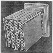
Folded wet aluminum electrolytic capacitor, Bell System 1929, view onto the folded anode, which was mounted in a squared housing (not shown) filled with liquid electrolyte

Two 8 μF, 525 V wound wet aluminum electrolytic capacitors in paper housing sealed with tar out of a 1930s radio.


Overlapping range of the applicationsEdit
These individual capacitors can perform their application independent of their affiliation to an above shown capacitor type, so that an overlapping range of applications between the different capacitor types exists.

Types and stylesEdit
Ceramic capacitorsEdit

A ceramic capacitor is a non-polarized fixed capacitor made out of two or more alternating layers of ceramic and metal in which the ceramic material acts as the dielectric and the metal acts as the electrodes. The ceramic material is a mixture of finely ground granules of paraelectric or ferroelectric materials, modified by mixed oxides that are necessary to achieve the capacitor's desired characteristics. The electrical behavior of the ceramic material is divided into two stability classes:
- Class 1 ceramic capacitors with high stability and low losses compensating the influence of temperature in resonant circuit application. Common EIA/IEC code abbreviations are C0G/NP0, P2G/N150, R2G/N220, U2J/N750 etc.
- Class 2 ceramic capacitors with high volumetric efficiency for buffer, by-pass and coupling applications Common EIA/IEC code abbreviations are: X7R/2XI, Z5U/E26, Y5V/2F4, X7S/2C1, etc.
The great plasticity of ceramic raw material works well for many special applications and enables an enormous diversity of styles, shapes and great dimensional spread of ceramic capacitors. The smallest discrete capacitor, for instance, is a "01005" chip capacitor with the dimension of only 0.4 mm × 0.2 mm.
The construction of ceramic multilayer capacitors with mostly alternating layers results in single capacitors connected in parallel. This configuration increases capacitance and decreases all losses and parasitic inductances. Ceramic capacitors are well-suited for high frequencies and high current pulse loads.
Because the thickness of the ceramic dielectric layer can be easily controlled and produced by the desired application voltage, ceramic capacitors are available with rated voltages up to the 30 kV range.
Some ceramic capacitors of special shapes and styles are used as capacitors for special applications, including RFI/EMI suppression capacitors for connection to supply mains, also known as safety capacitors,[8] X2Y® and three-terminal capacitors for bypassing and decoupling applications,[9][10] feed-through capacitors for noise suppression by low-pass filters[11] and ceramic power capacitors for transmitters and HF applications.[12][13]
- Diverse styles of ceramic capacitors

Multi-layer ceramic capacitors (MLCC chips) for SMD mounting

Ceramic X2Y® decoupling capacitors
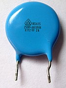
Ceramic EMI suppression capacitors for connection to the supply mains (safety capacitor)

High voltage ceramic power capacitor


Film capacitorsEdit

Film capacitors or plastic film capacitors are non-polarized capacitors with an insulating plastic film as the dielectric. The dielectric films are drawn to a thin layer, provided with metallic electrodes and wound into a cylindrical winding. The electrodes of film capacitors may be metallized aluminum or zinc, applied on one or both sides of the plastic film, resulting in metallized film capacitors or a separate metallic foil overlying the film, called film/foil capacitors.
Metallized film capacitors offer self-healing properties. Dielectric breakdowns or shorts between the electrodes do not destroy the component. The metallized construction makes it possible to produce wound capacitors with larger capacitance values (up to 100 µF and larger) in smaller cases than within film/foil construction.
Film/foil capacitors or metal foil capacitors use two plastic films as the dielectric. Each film is covered with a thin metal foil, mostly aluminium, to form the electrodes. The advantage of this construction is the ease of connecting the metal foil electrodes, along with an excellent current pulse strength.
A key advantage of every film capacitor's internal construction is direct contact to the electrodes on both ends of the winding. This contact keeps all current paths very short. The design behaves like a large number of individual capacitors connected in parallel, thus reducing the internal ohmic losses (equivalent series resistance or ESR) and equivalent series inductance (ESL). The inherent geometry of film capacitor structure results in low ohmic losses and a low parasitic inductance, which makes them suitable for applications with high surge currents (snubbers) and for AC power applications, or for applications at higher frequencies.
The plastic films used as the dielectric for film capacitors are polypropylene (PP), polyester (PET), polyphenylene sulfide (PPS), polyethylene naphthalate (PEN), and polytetrafluoroethylene (PTFE). Polypropylene has a market share of about 50% and polyester with about 40% are the most used film materials. The other 10% use all the other materials, including PPS and paper with roughly 3% each.[14][15]
| Film material, abbreviated codes | |||||
|---|---|---|---|---|---|
| Film characteristics | PET | PEN | PPS | PP | |
| Relative permittivity at 1 kHz | 3.3 | 3.0 | 3.0 | 2.2 | |
| Minimum film thickness (µm) | 0.7–0.9 | 0.9–1.4 | 1.2 | 2.4–3.0 | |
| Moisture absorption (%) | low | 0.4 | 0.05 | <0.1 | |
| Dielectric strength (V/µm) | 580 | 500 | 470 | 650 | |
| Commercial realized voltage proof (V/µm) | 280 | 300 | 220 | 400 | |
| DC voltage range (V) | 50–1,000 | 16–250 | 16–100 | 40–2,000 | |
| Capacitance range | 100 pF–22 µF | 100 pF–1 µF | 100 pF–0.47 µF | 100 pF–10 µF | |
| Application temperature range (°C) | −55 to +125 /+150 | −55 to +150 | −55 to +150 | −55 to +105 | |
| C/C0 versus temperature range (%) | ±5 | ±5 | ±1.5 | ±2.5 | |
| Dissipation factor (•10−4) | |||||
| at 1 kHz | 50–200 | 42–80 | 2–15 | 0.5–5 | |
| at 10 kHz | 110–150 | 54–150 | 2.5–25 | 2–8 | |
| at 100 kHz | 170–300 | 120–300 | 12–60 | 2–25 | |
| at 1 MHz | 200–350 | – | 18–70 | 4–40 | |
| Time constant RInsul•C (s) | at 25 °C | ≥10,000 | ≥10,000 | ≥10,000 | ≥100,000 |
| at 85 °C | 1,000 | 1,000 | 1,000 | 10,000 | |
| Dielectric absorption (%) | 0.2–0.5 | 1–1.2 | 0.05–0.1 | 0.01–0.1 | |
| Specific capacitance (nF•V/mm3) | 400 | 250 | 140 | 50 | |
Some film capacitors of special shapes and styles are used as capacitors for special applications, including RFI/EMI suppression capacitors for connection to the supply mains, also known as safety capacitors,[16] snubber capacitors for very high surge currents,[17] motor run capacitors and AC capacitors for motor-run applications.[18]
- High pulse current load is the most important feature of film capacitors so many of the available styles have special terminations for high currents

Radial style (single ended) for through-hole solder mounting on printed circuit boards

SMD style for printed circuit board surface mounting, with metallized contacts on two opposite edges

Radial style with heavy-duty solder terminals for snubber applications and high surge pulse loads
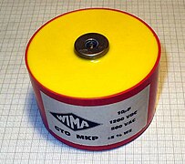
Heavy-duty snubber capacitor with screw terminals


Power film capacitorsEdit

A related type is the power film capacitor. The materials and construction techniques used for large power film capacitors mostly are similar to those of ordinary film capacitors. However, capacitors with high to very high power ratings for applications in power systems and electrical installations are often classified separately, for historical reasons. The standardization of ordinary film capacitors is oriented on electrical and mechanical parameters. The standardization of power capacitors by contrast emphasizes the safety of personnel and equipment, as given by the local regulating authority.
As modern electronic equipment gained the capacity to handle power levels that were previously the exclusive domain of "electrical power" components, the distinction between the "electronic" and "electrical" power ratings blurred. Historically, the boundary between these two families was approximately at a reactive power of 200 volt-amperes.
Film power capacitors mostly use polypropylene film as the dielectric. Other types include metallized paper capacitors (MP capacitors) and mixed dielectric film capacitors with polypropylene dielectrics. MP capacitors serve for cost applications and as field-free carrier electrodes (soggy foil capacitors) for high AC or high current pulse loads. Windings can be filled with an insulating oil or with epoxy resin to reduce air bubbles, thereby preventing short circuits.
They find use as converters to change voltage, current or frequency, to store or deliver abruptly electric energy or to improve the power factor. The rated voltage range of these capacitors is from approximately 120 V AC (capacitive lighting ballasts) to 100 kV.[19]
- Power film capacitors for applications in power systems, electrical installations and plants

Power film capacitor for AC power-factor correction (PFC), packaged in a cylindrical metal can
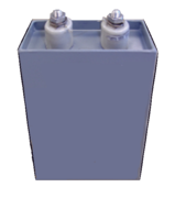
Power film capacitor in rectangular housing


75MVAR substation capacitor bank at 150 kV


Electrolytic capacitorsEdit

Electrolytic capacitors have a metallic anode covered with an oxidized layer used as dielectric. The second electrode is a non-solid (wet) or solid electrolyte. Electrolytic capacitors are polarized. Three families are available, categorized according to their dielectric.
- Aluminum electrolytic capacitors with aluminum oxide as dielectric
- Tantalum electrolytic capacitors with tantalum pentoxide as dielectric
- Niobium electrolytic capacitors with niobium pentoxide as dielectric.
The anode is highly roughened to increase the surface area. This and the relatively high permittivity of the oxide layer gives these capacitors very high capacitance per unit volume compared with film- or ceramic capacitors.
The permittivity of tantalum pentoxide is approximately three times higher than aluminium oxide, producing significantly smaller components. However, permittivity determines only the dimensions. Electrical parameters, especially conductivity, are established by the electrolyte's material and composition. Three general types of electrolytes are used:
- non solid (wet, liquid)—conductivity approximately 10 mS/cm and are the lowest cost
- solid manganese oxide—conductivity approximately 100 mS/cm offer high quality and stability
- solid conductive polymer (Polypyrrole or PEDOT:PSS)—conductivity approximately 100...500 S/cm,[20][21] offer ESR values as low as <10 mΩ
Internal losses of electrolytic capacitors, prevailing used for decoupling and buffering applications, are determined by the kind of electrolyte.
| Anode material | Electrolyte | Capacitance range (µF) | Max. rated voltage at 85 °C (V) | Upper categorie temperature (°C) | Specific ripple current (mA/mm3) 1) |
|---|---|---|---|---|---|
| Aluminum (roughened foil) | non solid, e.g. Ethylene glycol, DMF, DMA, GBL | 0.1–2,700,000 | 600 | 150 | 0.05–2.0 |
| solid, Manganese dioxide (MnO2 | 0.1–1,500 | 40 | 175 | 0.5–2.5 | |
| solid conductive polymer (e.g. PEDOT:PSS) | 10–1,500 | 250 | 125 | 10–30 | |
| Tantalum (roughened foil) | non solid Sulfuric acid | 0.1–1,000 | 630 | 125 | – |
| Tantalum (sintered) | non solid sulfuric acid | 0.1–15,000 | 150 | 200 | – |
| solid Manganese dioxide (MnO2 | 0.1–3,300 | 125 | 150 | 1.5–15 | |
| solid conductive polymer (e.g. PEDOT:PSS) | 10–1,500 | 35 | 125 | 10–30 | |
| Niobium or niobium oxide (sintered) | solid Manganese dioxide (MnO2 | 1–1,500 | 10 | 125 | 5–20 |
| |||||
The large capacitance per unit volume of electrolytic capacitors make them valuable in relatively high-current and low-frequency electrical circuits, e.g. in power supply filters for decoupling unwanted AC components from DC power connections or as coupling capacitors in audio amplifiers, for passing or bypassing low-frequency signals and storing large amounts of energy. The relatively high capacitance value of an electrolytic capacitor combined with the very low ESR of the polymer electrolyte of polymer capacitors, especially in SMD styles, makes them a competitor to MLC chip capacitors in personal computer power supplies.
Bipolar aluminum electrolytic capacitors (also called Non-Polarized capacitors) contain two anodized aluminium foils, behaving like two capacitors connected in series opposition.
Electrolytic capacitors for special applications include motor start capacitors,[22] flashlight capacitors[23] and audio frequency capacitors.[24]
- Schematic representation

Schematic representation of the structure of a wound aluminum electrolytic capacitor with non solid (liquid) electrolyte

Schematic representation of the structure of a sintered tantalum electrolytic capacitor with solid electrolyte and the cathode contacting layers


- Aluminum, tantalum and niobium electrolytic capacitors

Axial, radial (single ended) and V-chip styles of aluminum electrolytic capacitors
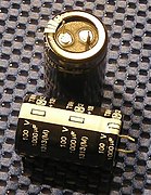
Snap-in style of aluminum electrolytic capacitors for power applications

SMD style for surface mounting of aluminum electrolytic capacitors with polymer electrolyte

Tantalum electrolytic chip capacitors for surface mounting


SupercapacitorsEdit


Supercapacitors (SC),[25] comprise a family of electrochemical capacitors. Supercapacitor, sometimes called ultracapacitor is a generic term for electric double-layer capacitors (EDLC), pseudocapacitors and hybrid capacitors. They don't have a conventional solid dielectric. The capacitance value of an electrochemical capacitor is determined by two storage principles, both of which contribute to the total capacitance of the capacitor:[26][27][28]
- Double-layer capacitance – Storage is achieved by separation of charge in a Helmholtz double layer at the interface between the surface of a conductor and an electrolytic solution. The distance of separation of charge in a double-layer is on the order of a few Angstroms (0.3–0.8 nm). This storage is electrostatic in origin.[1]
- Pseudocapacitance – Storage is achieved by redox reactions, electrosorbtion or intercalation on the surface of the electrode or by specifically adsorpted ions that results in a reversible faradaic charge-transfer. The pseudocapacitance is faradaic in origin.[1]
The ratio of the storage resulting from each principle can vary greatly, depending on electrode design and electrolyte composition. Pseudocapacitance can increase the capacitance value by as much as an order of magnitude over that of the double-layer by itself.[25]
Supercapacitors are divided into three families, based on the design of the electrodes:
- Double-layer capacitors – with carbon electrodes or derivates with much higher static double-layer capacitance than the faradaic pseudocapacitance
- Pseudocapacitors – with electrodes out of metal oxides or conducting polymers with a high amount of faradaic pseudocapacitance
- Hybrid capacitors – capacitors with special and asymmetric electrodes that exhibit both significant double-layer capacitance and pseudocapacitance, such as lithium-ion capacitors
Supercapacitors bridge the gap between conventional capacitors and rechargeable batteries. They have the highest available capacitance values per unit volume and the greatest energy density of all capacitors. They support up to 12,000 farads/1.2 volt,[29] with capacitance values up to 10,000 times that of electrolytic capacitors.[25] While existing supercapacitors have energy densities that are approximately 10% of a conventional battery, their power density is generally 10 to 100 times greater. Power density is defined as the product of energy density, multiplied by the speed at which the energy is delivered to the load. The greater power density results in much shorter charge/discharge cycles than a battery is capable, and a greater tolerance for numerous charge/discharge cycles. This makes them well-suited for parallel connection with batteries, and may improve battery performance in terms of power density.
Within electrochemical capacitors, the electrolyte is the conductive connection between the two electrodes, distinguishing them from electrolytic capacitors, in which the electrolyte only forms the cathode, the second electrode.
Supercapacitors are polarized and must operate with correct polarity. Polarity is controlled by design with asymmetric electrodes, or, for symmetric electrodes, by a potential applied during the manufacturing process.
Supercapacitors support a broad spectrum of applications for power and energy requirements, including:
- Low supply current during longer times for memory backup in (SRAMs) in electronic equipment
- Power electronics that require very short, high current, as in the KERSsystem in Formula 1 cars
- Recovery of braking energy for vehicles such as buses and trains
Supercapacitors are rarely interchangeable, especially those with higher energy densities. IEC standard 62391-1 Fixed electric double layer capacitors for use in electronic equipment identifies four application classes:
- Class 1, Memory backup, discharge current in mA = 1 • C (F)
- Class 2, Energy storage, discharge current in mA = 0.4 • C (F) • V (V)
- Class 3, Power, discharge current in mA = 4 • C (F) • V (V)
- Class 4, Instantaneous power, discharge current in mA = 40 • C (F) • V (V)
Exceptional for electronic components like capacitors are the manifold different trade or series names used for supercapacitors like: APowerCap, BestCap, BoostCap, CAP-XX, DLCAP, EneCapTen, EVerCAP, DynaCap, Faradcap, GreenCap, Goldcap, HY-CAP, Kapton capacitor, Super capacitor, SuperCap, PAS Capacitor, PowerStor, PseudoCap, Ultracapacitor making it difficult for users to classify these capacitors.
- Double-layer, Lithium-Ion and supercapacitors
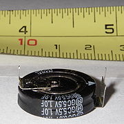
Double-layer capacitor with 1 F at 5.5 V for data retention when power is off.

Radial (single ended) style of lithium ion capacitors for high energy density
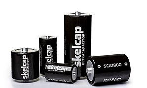
Supercapacitors


Class X and Class Y capacitorsEdit
Many safety regulations mandate that Class X or Class Y capacitors must be used whenever a "fail-to-short-circuit" could put humans in danger, to guarantee galvanic isolation even when the capacitor fails.
Lightning strikes and other sources cause high voltage surges in mains power. Safety capacitors protect humans and devices from high voltage surges by shunting the surge energy to ground.[30]
In particular, safety regulations mandate a particular arrangement of Class X and Class Y mains filtering capacitors.[31]
In principle, any dielectric could be used to build Class X and Class Y capacitors; perhaps by including an internal fuse to improve safety.[32][33][34][35] In practice, capacitors that meet Class X and Class Y specifications are typically ceramic RFI/EMI suppression capacitors or plastic film RFI/EMI suppression capacitors.
Miscellaneous capacitorsEdit
Beneath the above described capacitors covering more or less nearly the total market of discrete capacitors some new developments or very special capacitor types as well as older types can be found in electronics.
Integrated capacitorsEdit
- Integrated capacitors—in integrated circuits, nano-scale capacitors can be formed by appropriate patterns of metallization on an isolating substrate. They may be packaged in multiple capacitor arrays with no other semiconductive parts as discrete components.[36]
- Glass capacitors—First Leyden jar capacitor was made of glass, As of 2012 glass capacitors were in use as SMD version for applications requiring ultra-reliable and ultra-stable service.
Power capacitorsEdit
- Vacuum capacitors—used in high power RF transmitters
- SF6 gas filled capacitors—used as capacitance standard in measuring bridge circuits
Special capacitorsEdit
- Printed circuit boards—metal conductive areas in different layers of a multi-layer printed circuit board can act as a highly stable capacitor in Distributed-element filters. It is common industry practice to fill unused areas of one PCB layer with the ground conductor and another layer with the power conductor, forming a large distributed capacitor between the layers.
- Wire—2 pieces of insulated wire twisted together. Capacitance values usually range from 3 pF to 15 pF. Used in homemade VHF circuits for oscillation feedback.
Specialized devices such as built-in capacitors with metal conductive areas in different layers of a multi-layer printed circuit board and kludges such as twisting together two pieces of insulated wire also exist.
Capacitors made by twisting 2 pieces of insulated wire together are called gimmick capacitors. Gimmick capacitors were used in commercial and amateur radio receivers.[37][38][39][40][41]
Obsolete capacitorsEdit
- Leyden jars the earliest known capacitor
- Clamped mica capacitors—the first capacitors with stable frequency behavior and low losses, used for military radio applications during World War II
- Air-gap capacitors—used by the first spark-gap transmitters
- Miscellaneous capacitors
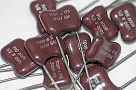
Some 1 nF × 500 VDC rated silver mica capacitors

Vacuum capacitor with uranium glass encapsulation


Variable capacitorsEdit
Variable capacitors may have their capacitance changed by mechanical motion. Generally two versions of variable capacitors has to be to distinguished
- Tuning capacitor – variable capacitor for intentionally and repeatedly tuning an oscillator circuit in a radio or another tuned circuit
- Trimmer capacitor – small variable capacitor usually for one-time oscillator circuit internal adjustment
Variable capacitors include capacitors that use a mechanical construction to change the distance between the plates, or the amount of plate surface area which overlaps. They mostly use air as dielectric medium.
Semiconductive variable capacitance diodes are not capacitors in the sense of passive components but can change their capacitance as a function of the applied reverse bias voltage and are used like a variable capacitor. They have replaced much of the tuning and trimmer capacitors.
- Variable capacitors

Air gap tuning capacitor

Vacuum tuning capacitor

Trimmer capacitor for through hole mounting

Trimmer capacitor for surface mounting


Comparison of typesEdit
| Capacitor type | Dielectric | Features/applications | Disadvantages |
|---|---|---|---|
| Ceramic capacitors | |||
| Ceramic Class 1 capacitors | paraelectric ceramic mixture of Titanium dioxide modified by additives | Predictable linear and low capacitance change with operating temperature. Excellent high frequency characteristics with low losses. For temperature compensation in resonant circuit application. Available in voltages up to 15,000 V | Low permittivity ceramic, capacitors with low volumetric efficiency, larger dimensions than Class 2 capacitors |
| Ceramic Class 2 capacitors | ferroelectric ceramic mixture of barium titanate and suitable additives | High permittivity, high volumetric efficiency, smaller dimensions than Class 1 capacitors. For buffer, by-pass and coupling applications. Available in voltages up to 50,000 V. | Lower stability and higher losses than Class 1. Capacitance changes with change in applied voltage, with frequency and with aging effects. Slightly microphonic |
| Film capacitors | |||
| Metallized film capacitors | PP, PET, PEN, PPS, (PTFE) | Metallized film capacitors are significantly smaller in size than film/foil versions and have self-healing properties. | Thin metallized electrodes limit the maximum current carrying capability respectively the maximum possible pulse voltage. |
| Film/foil film capacitors | PP, PET, PTFE | Film/foil film capacitors have the highest surge ratings/pulse voltage, respectively. Peak currents are higher than for metallized types. | No self-healing properties: internal short may be disabling. Larger dimensions than metallized alternative. |
| Polypropylene (PP) film capacitors | Polypropylene | Most popular film capacitor dielectric. Predictable linear and low capacitance change with operating temperature. Suitable for applications in Class-1 frequency-determining circuits and precision analog applications. Very narrow capacitances. Extremely low dissipation factor. Low moisture absorption, therefore suitable for "naked" designs with no coating. High insulation resistance. Usable in high power applications such as snubber or IGBT. Used also in AC power applications, such as in motors or power-factor correction. Very low dielectric losses. High frequency and high power applications such as induction heating. Widely used for safety/EMI suppression, including connection to power supply mains. | Maximum operating temperature of 105 °C. Relatively low permittivity of 2.2. PP film capacitors tend to be larger than other film capacitors. More susceptible to damage from transient over-voltages or voltage reversals than oil-impregnated MKV-capacitors for pulsed power applications. |
| Polyester (PET) film (Mylar) capacitors | Polyethylene terephthalate, Polyester (Hostaphan®, Mylar®) | Smaller in size than functionally comparable polypropylene film capacitors. Low moisture absorption. Have almost completely replaced metallized paper and polystyrene film for most DC applications. Mainly used for general purpose applications or semi-critical circuits with operating temperatures up to 125 °C. Operating voltages up to 60,000 V DC. | Usable at low (AC power) frequencies. Limited use in power electronics due to higher losses with increasing temperature and frequency. |
| Polyethylene naphthalate (PEN) film capacitors | Polyethylene naphthalate (Kaladex®) | Better stability at high temperatures than PET. More suitable for high temperature applications and for SMD packaging. Mainly used for non-critical filtering, coupling and decoupling, because temperature dependencies are not significant. | Lower relative permittivity and lower dielectric strength imply larger dimensions for a given capacitance and rated voltage than PET. |
| Polyphenylene Sulfide (PPS) film capacitors | Polyphenylene (Torelina®) | Small temperature dependence over the entire temperature range and a narrow frequency dependence in a wide frequency range. Dissipation factor is quite small and stable. Operating temperatures up to 270 °C. Suitable for SMD. Tolerate increased reflow soldering temperatures for lead-free soldering mandated by the RoHS 2002/95/European Union directive | Above 100 °C, the dissipation factor increases, increasing component temperature, but can operate without degradation. Cost is usually higher than PP. |
| Polytetrafluoroethylene (PTFE) (Teflon film) capacitors | Polytetrafluoroethylene (Teflon®) | Lowest loss solid dielectric. Operating temperatures up to 250 °C. Extremely high insulation resistance. Good stability. Used in mission-critical applications. | Large size (due to low dielectric constant). Higher cost than other film capacitors. |
| Polycarbonate (PC) film capacitors | Polycarbonate | Almost completely replaced by PP | Limited manufacturers |
| Polystyrene (PS) film capacitors | Polystyrene (Styroflex) | Good thermal stability, high insulation, low distortion[42] but unsuited to SMT and now almost completely replaced by PET | Limited manufacturers |
| Polysulphone film capacitors | Polysulfone | Similar to polycarbonate. Withstand full voltage at comparatively higher temperatures. | Only development, no series found (2012) |
| Polyamide film capacitors | Polyamide | Operating temperatures of up to 200 °C. High insulation resistance. Good stability. Low dissipation factor. | Only development, no series found (2012) |
| Polyimide film (Kapton) capacitors | Polyimide (Kapton) | Highest dielectric strength of any known plastic film dielectric. | Only development, no series found (2012) |
| Film-based power capacitors | |||
| Metallized paper power capacitors | Paper impregnated with insulating oil or epoxy resin | Self-healing properties. Originally impregnated with wax, oil or epoxy. Oil-Kraft paper version used in certain high voltage applications. Mostly replaced by PP. | Large size. Highly hygroscopic, absorbing moisture from the atmosphere despite plastic enclosures and impregnates. Moisture increases dielectric losses and decreases insulation resistance. |
| Paper film/foil power capacitors | Kraft paper impregnated with oil | Paper covered with metal foils as electrodes. Low cost. Intermittent duty, high discharge applications. | Physically large and heavy. Significantly lower energy density than PP dielectric. Not self-healing. Potential catastrophic failure due to high stored energy. |
| PP dielectric, field-free paper power capacitors (MKV power capacitors) | Double-sided (field-free) metallized paper as electrode carrier. PP as dielectric, impregnated with insulating oil, epoxy resin or insulating gas | Self-healing. Very low losses. High insulation resistance. High inrush current strength. High thermal stability. Heavy duty applications such as commutating with high reactive power, high frequencies and a high peak current load and other AC applications. | Physically larger than PP power capacitors. |
| Single- or double-sided metallized PP power capacitors | PP as dielectric, impregnated with insulating oil, epoxy resin or insulating gas | Highest capacitance per volume power capacitor. Self-healing. Broad range of applications such as general-purpose, AC capacitors, motor capacitors, smoothing or filtering, DC links, snubbing or clamping, damping AC, series resonant DC circuits, DC discharge, AC commutation, AC power-factor correction. | critical for reliable high voltage operation and very high inrush current loads, limited heat resistance (105 °C) |
| PP film/foil power capacitors | Impregnated PP or insulating gas, insulating oil, epoxy resin or insulating gas | Highest inrush current strength | Larger than the PP metallized versions. Not self-healing. |
| Electrolytic capacitors | |||
| Electrolytic capacitors with non solid (wet, liquid) electrolyte | Aluminum oxide Al2O3 | Very large capacitance to volume ratio. Capacitance values up to 2,700,000 µF/6.3 V. Voltage up to 550 V. Lowest cost per capacitance/voltage values. Used where low losses and high capacitance stability are not of major importance, especially for lower frequencies, such as by-pass, coupling, smoothing and buffer applications in power supplies and DC-links. | Polarized. Significant leakage. Relatively high ESR and ESL values, limiting high ripple current and high frequency applications. Lifetime calculation required because drying out phenomenon. Vent or burst when overloaded, overheated or connected wrong polarized. Water based electrolyte may vent at end-of-life, showing failures like "capacitor plague" |
| Tantalum pentoxide Ta2O5 | Wet tantalum electrolytic capacitors (wet slug)[43] Lowest leakage among electrolytics. Voltage up to 630 V (tantalum film) or 125 V (tantalum sinter body). Hermetically sealed. Stable and reliable. Military and space applications. | Polarized. Violent explosion when voltage, ripple current or slew rates are exceeded, or under reverse voltage. Expensive. | |
| Electrolytic capacitors with solid Manganese dioxide electrolyte | Aluminum oxide Al 2O 3 Tantalum pentoxide Ta2O5, Niobium pentoxide Nb 2O 5 | Tantalum and niobium with smaller dimensions for a given capacitance/voltage vs aluminum. Stable electrical parameters. Good long-term high temperature performance. Lower ESR lower than non-solid (wet) electrolytics. | Polarized. About 125 V. Low voltage and limited, transient, reverse or surge voltage tolerance. Possible combustion upon failure. ESR much higher than conductive polymer electrolytics. Manganese expected to be replaced by polymer. |
| Electrolytic capacitors with solid Polymer electrolyte (Polymer capacitors) | Aluminum oxide Al 2O 3, Tantalum pentoxide Ta2O5, Niobium pentoxide Nb 2O 5 | Greatly reduced ESR compared with manganese or non-solid (wet) elelectrolytics. Higher ripple current ratings. Extended operational life. Stable electrical parameters. Self-healing.[44] Used for smoothing and buffering in smaller power supplies especially in SMD. | Polarized. Highest leakage current among electrolytics. Higher prices than non-solid or manganese dioxide. Voltage limited to about 100 V. Explodes when voltage, current, or slew rates are exceeded or under reverse voltage. |
| Supercapacitors | |||
| Supercapacitors Pseudocapacitors | Helmholtz double-layer plus faradaic pseudo-capacitance | Energy density typically tens to hundreds of times greater than conventional electrolytics. More comparable to batteries than to other capacitors. Large capacitance/volume ratio. Relatively low ESR. Thousands of farads. RAM memory backup. Temporary power during battery replacement. Rapidly absorbs/delivers much larger currents than batteries. Hundreds of thousands of charge/discharge cycles. Hybrid vehicles. Recuperation | Polarized. Low operating voltage per cell. (Stacked cells provide higher operating voltage.) Relatively high cost. |
| Hybrid capacitors Lithium ion capacitors (LIC) | Helmholtz double-layer plus faradaic pseudo-capacitance. Anode doped with lithium ions. | Higher operating voltage. Higher energy density than common EDLCs, but smaller than lithium ion batteries (LIB). No thermal runaway reactions. | Polarized. Low operating voltage per cell. (Stacked cells provide higher operating voltage.) Relatively high cost. |
| Miscellaneous capacitors | |||
| Air gap capacitors | Air | Low dielectric loss. Used for resonating HF circuits for high power HF welding. | Physically large. Relatively low capacitance. |
| Vacuum capacitors | Vacuum | Extremely low losses. Used for high voltage, high power RF applications, such as transmitters and induction heating. Self-healing if arc-over current is limited. | Very high cost. Fragile. Large. Relatively low capacitance. |
| SF 6-gas filled capacitors | SF 6 gas | High precision.[45] Extremely low losses. Very high stability. Up to 1600 kV rated voltage. Used as capacitance standard in measuring bridge circuits. | Very high cost |
| Metallized mica (silver mica) capacitors | Mica | Very high stability. No aging. Low losses. Used for HF and low VHF RF circuits and as capacitance standard in measuring bridge circuits. Mostly replaced by Class 1 ceramic capacitors | Higher cost than class 1 ceramic capacitors |
| Glass capacitors | Glass | Better stability and frequency than silver mica. Ultra-reliable. Ultra-stable. Resistant to nuclear radiation. Operating temperature: −75 °C to +200 °C and even short overexposure to +250 °C.[46] | Higher cost than class 1 ceramic |
| Integrated capacitors | oxide-nitride-oxide (ONO) | Thin (down to 100 µm). Smaller footprint than most MLCC. Low ESL. Very high stability up to 200 °C. High reliability | Customized production |
| Variable capacitors | |||
| Air gap tuning capacitors | Air | Circular or various logarithmic cuts of the rotor electrode for different capacitance curves. Split rotor or stator cut for symmetric adjustment. Ball bearing axis for noise reduced adjustment. For high professional devices. | Large dimensions. High cost. |
| Vacuum tuning capacitors | Vacuum | Extremely low losses. Used for high voltage, high power RF applications, such as transmitters and induction heating. Self-healing if arc-over current is limited. | Very high cost. Fragile. Large dimensions. |
| SF 6 gas filled tuning capacitor | SF 6 | Extremely low losses. Used for very high voltage high power RF applications. | Very high cost, fragile, large dimensions |
| Air gap trimmer capacitors | Air | Mostly replaced by semiconductive variable capacitance diodes | High cost |
| Ceramic trimmer capacitors | Class 1 ceramic | Linear and stable frequency behavior over wide temperature range | High cost |
Electrical characteristicsEdit
Series-equivalent circuitEdit

Discrete capacitors deviate from the ideal capacitor. An ideal capacitor only stores and releases electrical energy, with no dissipation. Capacitor components have losses and parasitic inductive parts. These imperfections in material and construction can have positive implications such as linear frequency and temperature behavior in class 1 ceramic capacitors. Conversely, negative implications include the non-linear, voltage-dependent capacitance in class 2 ceramic capacitors or the insufficient dielectric insulation of capacitors leading to leakage currents.
All properties can be defined and specified by a series equivalent circuit composed out of an idealized capacitance and additional electrical components which model all losses and inductive parameters of a capacitor. In this series-equivalent circuit the electrical characteristics are defined by:
- C, the capacitance of the capacitor
- Rinsul, the insulation resistance of the dielectric, not to be confused with the insulation of the housing
- Rleak, the resistance representing the leakage current of the capacitor
- RESR, the equivalent series resistance which summarizes all ohmic losses of the capacitor, usually abbreviated as "ESR"
- LESL, the equivalent series inductance which is the effective self-inductance of the capacitor, usually abbreviated as "ESL".
Using a series equivalent circuit instead of a parallel equivalent circuit is specified by IEC/EN 60384-1.
Standard capacitance values and tolerancesEdit
The rated capacitance CR or nominal capacitance CN is the value for which the capacitor has been designed. Actual capacitance depends on the measured frequency and ambient temperature. Standard measuring conditions are a low-voltage AC measuring method at a temperature of 20 °C with frequencies of
- 100 kHz, 1 MHz (preferred) or 10 MHz for non-electrolytic capacitors with CR ≤ 1 nF:
- 1 kHz or 10 kHz for non-electrolytic capacitors with 1 nF < CR ≤ 10 μF
- 100/120 Hz for electrolytic capacitors
- 50/60 Hz or 100/120 Hz for non-electrolytic capacitors with CR > 10 μF
For supercapacitors a voltage drop method is applied for measuring the capacitance value. .
Capacitors are available in geometrically increasing preferred values (E series standards) specified in IEC/EN 60063. According to the number of values per decade, these were called the E3, E6, E12, E24 etc. series. The range of units used to specify capacitor values has expanded to include everything from pico- (pF), nano- (nF) and microfarad (µF) to farad (F). Millifarad and kilofarad are uncommon.
The percentage of allowed deviation from the rated value is called tolerance. The actual capacitance value should be within its tolerance limits, or it is out of specification. IEC/EN 60062 specifies a letter code for each tolerance.
| E series | Tolerance | |||
|---|---|---|---|---|
| CR > 10 pF | Letter code | CR < 10 pF | Letter code | |
| E 96 | 1% | F | 0.1 pF | B |
| E 48 | 2% | G | 0.25 pF | C |
| E 24 | 5% | J | 0.5 pF | D |
| E 12 | 10% | K | 1 pF | F |
| E 6 | 20% | M | 2 pF | G |
| E3 | −20/+50% | S | - | - |
| −20/+80% | Z | - | - | |
The required tolerance is determined by the particular application. The narrow tolerances of E24 to E96 are used for high-quality circuits such as precision oscillators and timers. General applications such as non-critical filtering or coupling circuits employ E12 or E6. Electrolytic capacitors, which are often used for filtering and bypassing capacitors mostly have a tolerance range of ±20% and need to conform to E6 (or E3) series values.
Temperature dependenceEdit
Capacitance typically varies with temperature. The different dielectrics express great differences in temperature sensitivity. The temperature coefficient is expressed in parts per million (ppm) per degree Celsius for class 1 ceramic capacitors or in % over the total temperature range for all others.
| Type of capacitor, dielectric material | Temperature coefficient C/C0 | Application temperature range |
|---|---|---|
| Ceramic capacitor class 1 paraelectric NP0 | ± 30 ppm/K (±0.5%) | −55 to +125 °C |
| Ceramic capacitor class 2 ferroelectric X7R | ±15% | −55 to +125 °C |
| Ceramic capacitor class 2, ferroelectric Y5V | +22% / −82 % | −30 to +85 °C |
| Film capacitor Polypropylene ( PP) | ±2.5% | −55 to +85/105 °C |
| Film capacitor Polyethylen terephthalate, Polyester (PET) | +5% | −55 to +125/150 °C |
| Film capacitor Polyphenylene sulfide (PPS) | ±1.5% | −55 to +150 °C |
| Film capacitor Polyethylene naphthalate (PEN) | ±5% | −40 to +125/150 °C |
| Film capacitor Polytetrafluoroethylene (PTFE) | ? | −40 to +130 °C |
| Metallized paper capacitor (impregnated) | ±10% | −25 to +85 °C |
| Aluminum electrolytic capacitor Al2O3 | ±20% | −40 to +85/105/125 °C |
| Tantalum electrolytic capacitor Ta2O5 | ±20% | −40 to +125 °C |
Frequency dependenceEdit
Most discrete capacitor types have more or less capacitance changes with increasing frequencies. The dielectric strength of class 2 ceramic and plastic film diminishes with rising frequency. Therefore, their capacitance value decreases with increasing frequency. This phenomenon for ceramic class 2 and plastic film dielectrics is related to dielectric relaxation in which the time constant of the electrical dipoles is the reason for the frequency dependence of permittivity. The graphs below show typical frequency behavior of the capacitance for ceramic and film capacitors.
- Frequency dependence of capacitance for ceramic and film capacitors

Frequency dependence of capacitance for ceramic class 2 capacitors (NP0 class 1 for comparisation)
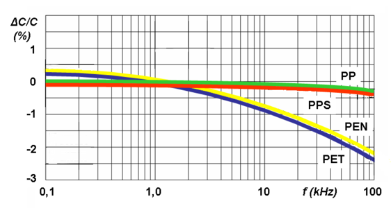
Frequency dependence of capacitance for film capacitors with different film materials


For electrolytic capacitors with non-solid electrolyte, mechanical motion of the ions occurs. Their movability is limited so that at higher frequencies not all areas of the roughened anode structure are covered with charge-carrying ions. As higher the anode structure is roughened as more the capacitance value decreases with increasing frequency. Low voltage types with highly roughened anodes display capacitance at 100 kHz approximately 10 to 20% of the value measured at 100 Hz.
Voltage dependenceEdit
Capacitance may also change with applied voltage. This effect is more prevalent in class 2 ceramic capacitors. The permittivity of ferroelectric class 2 material depends on the applied voltage. Higher applied voltage lowers permittivity. The change of capacitance can drop to 80% of the value measured with the standardized measuring voltage of 0.5 or 1.0 V. This behavior is a small source of non-linearity in low-distortion filters and other analog applications. In audio applications this can cause distortion (measured using THD).
Film capacitors and electrolytic capacitors have no significant voltage dependence.
- Voltage dependence of capacitance for some different class 2 ceramic capacitors

Simplified diagram of the change in capacitance as a function of the applied voltage for 25-V capacitors in different kind of ceramic grades

Simplified diagram of the change in capacitance as a function of applied voltage for X7R ceramics with different rated voltages


Rated and category voltageEdit

The voltage at which the dielectric becomes conductive is called the breakdown voltage, and is given by the product of the dielectric strength and the separation between the electrodes. The dielectric strength depends on temperature, frequency, shape of the electrodes, etc. Because a breakdown in a capacitor normally is a short circuit and destroys the component, the operating voltage is lower than the breakdown voltage. The operating voltage is specified such that the voltage may be applied continuously throughout the life of the capacitor.
In IEC/EN 60384-1 the allowed operating voltage is called "rated voltage" or "nominal voltage". The rated voltage (UR) is the maximum DC voltage or peak pulse voltage that may be applied continuously at any temperature within the rated temperature range.
The voltage proof of nearly all capacitors decreases with increasing temperature. Some applications require a higher temperature range. Lowering the voltage applied at a higher temperature maintains safety margins. For some capacitor types therefore the IEC standard specify a second "temperature derated voltage" for a higher temperature range, the "category voltage". The category voltage (UC) is the maximum DC voltage or peak pulse voltage that may be applied continuously to a capacitor at any temperature within the category temperature range.
The relation between both voltages and temperatures is given in the picture right.
ImpedanceEdit

In general, a capacitor is seen as a storage component for electric energy. But this is only one capacitor function. A capacitor can also act as an AC resistor. In many cases the capacitor is used as a decoupling capacitor to filter or bypass undesired biased AC frequencies to the ground. Other applications use capacitors for capacitive coupling of AC signals; the dielectric is used only for blocking DC. For such applications the AC resistance is as important as the capacitance value.
The frequency dependent AC resistance is called impedance 

The magnitude 


In capacitor data sheets, only the impedance magnitude |Z| is specified, and simply written as "Z" so that the formula for the impedance can be written in Cartesian form

where the real part of impedance is the resistance 


As shown in a capacitor's series-equivalent circuit, the real component includes an ideal capacitor 

To calculate the impedance the resistance has to be added geometrically and then is given by
- . The impedance is a measure of the capacitor's ability to pass alternating currents. In this sense the impedance can be used like Ohms law
to calculate either the peak or the effective value of the current or the voltage.
In the special case of resonance, in which the both reactive resistances
- and
have the same value ( ), then the impedance will only be determined by .
The impedance specified in the datasheets often show typical curves for the different capacitance values. With increasing frequency as the impedance decreases down to a minimum. The lower the impedance, the more easily alternating currents can be passed through the capacitor. At the apex, the point of resonance, where XC has the same value than XL, the capacitor has the lowest impedance value. Here only the ESR determines the impedance. With frequencies above the resonance the impedance increases again due to the ESL of the capacitor. The capacitor becomes an inductance.
As shown in the graph, the higher capacitance values can fit the lower frequencies better while the lower capacitance values can fit better the higher frequencies.
Aluminum electrolytic capacitors have relatively good decoupling properties in the lower frequency range up to about 1 MHz due to their large capacitance values. This is the reason for using electrolytic capacitors in standard or switched-mode power supplies behind the rectifier for smoothing application.
Ceramic and film capacitors are already out of their smaller capacitance values suitable for higher frequencies up to several 100 MHz. They also have significantly lower parasitic inductance, making them suitable for higher frequency applications, due to their construction with end-surface contacting of the electrodes. To increase the range of frequencies, often an electrolytic capacitor is connected in parallel with a ceramic or film capacitor.[47]
Many new developments are targeted at reducing parasitic inductance (ESL). This increases the resonance frequency of the capacitor and, for example, can follow the constantly increasing switching speed of digital circuits. Miniaturization, especially in the SMD multilayer ceramic chip capacitors (MLCC), increases the resonance frequency. Parasitic inductance is further lowered by placing the electrodes on the longitudinal side of the chip instead of the lateral side. The "face-down" construction associated with multi-anode technology in tantalum electrolytic capacitors further reduced ESL. Capacitor families such as the so-called MOS capacitor or silicon capacitors offer solutions when capacitors at frequencies up to the GHz range are needed.
Inductance (ESL) and self-resonant frequencyEdit
ESL in industrial capacitors is mainly caused by the leads and internal connections used to connect the capacitor plates to the outside world. Large capacitors tend to have higher ESL than small ones because the distances to the plate are longer and every mm counts as an inductance.
For any discrete capacitor, there is a frequency above DC at which it ceases to behave as a pure capacitor. This frequency, where is as high as , is called the self-resonant frequency. The self-resonant frequency is the lowest frequency at which the impedance passes through a minimum. For any AC application the self-resonant frequency is the highest frequency at which capacitors can be used as a capacitive component.
This is critically important for decoupling high-speed logic circuits from the power supply. The decoupling capacitor supplies transient current to the chip. Without decouplers, the IC demands current faster than the connection to the power supply can supply it, as parts of the circuit rapidly switch on and off. To counter this potential problem, circuits frequently use multiple bypass capacitors—small (100 nF or less) capacitors rated for high frequencies, a large electrolytic capacitor rated for lower frequencies and occasionally, an intermediate value capacitor.
Ohmic losses, ESR, dissipation factor, and quality factorEdit
The summarized losses in discrete capacitors are ohmic AC losses. DC losses are specified as "leakage current" or "insulating resistance" and are negligible for an AC specification. AC losses are non-linear, possibly depending on frequency, temperature, age or humidity. The losses result from two physical conditions:
- line losses including internal supply line resistances, the contact resistance of the electrode contact, line resistance of the electrodes, and in "wet" aluminum electrolytic capacitors and especially supercapacitors, the limited conductivity of liquid electrolytes and
- dielectric losses from dielectric polarization.
The largest share of these losses in larger capacitors is usually the frequency dependent ohmic dielectric losses. For smaller components, especially for wet electrolytic capacitors, conductivity of liquid electrolytes may exceed dielectric losses. To measure these losses, the measurement frequency must be set. Since commercially available components offer capacitance values cover 15 orders of magnitude, ranging from pF (10−12 F) to some 1000 F in supercapacitors, it is not possible to capture the entire range with only one frequency. IEC 60384-1 states that ohmic losses should be measured at the same frequency used to measure capacitance. These are:
- 100 kHz, 1 MHz (preferred) or 10 MHz for non-electrolytic capacitors with CR ≤ 1 nF:
- 1 kHz or 10 kHz for non-electrolytic capacitors with 1 nF < CR ≤ 10 μF
- 100/120 Hz for electrolytic capacitors
- 50/60 Hz or 100/120 Hz for non-electrolytic capacitors with CR > 10 μF
A capacitor's summarized resistive losses may be specified either as ESR, as a dissipation factor(DF, tan δ), or as quality factor (Q), depending on application requirements.
Capacitors with higher ripple current 
The losses of film capacitors and some class 2 ceramic capacitors are mostly specified with the dissipation factor tan δ. These capacitors have smaller losses than electrolytic capacitors and mostly are used at higher frequencies up to some hundred MHz. However the numeric value of the dissipation factor, measured at the same frequency, is independent of the capacitance value and can be specified for a capacitor series with a range of capacitance. The dissipation factor is determined as the tangent of the reactance (
If the inductance 

Capacitors with very low losses, such as ceramic Class 1 and Class 2 capacitors, specify resistive losses with a quality factor (Q). Ceramic Class 1 capacitors are especially suitable for LC resonant circuits with frequencies up to the GHz range, and precise high and low pass filters. For an electrically resonant system, Q represents the effect of electrical resistance and characterizes a resonator's bandwidth 


A high Q value is for resonant circuits a mark of the quality of the resonance.
| Capacitor type | Capacitance (pF) | ESR at 100 kHz (mΩ) | ESR at 1 MHz (mΩ) | tan δ at 1 MHz (10−4) | Quality factor |
|---|---|---|---|---|---|
| Silicon capacitor[48] | 560 | 400 | — | 2,5 | 4000 |
| Mica capacitor[49] | 1000 | 650 | 65 | 4 | 2500 |
| Class 1 ceramic capacitor (NP0)[50] | 1000 | 1600 | 160 | 10 | 1000 |
Limiting current loadsEdit
A capacitor can act as an AC resistor, coupling AC voltage and AC current between two points. Every AC current flow through a capacitor generates heat inside the capacitor body. These dissipation power loss 


The same power loss can be written with the dissipation factor 

The internal generated heat has to be distributed to the ambient. The temperature of the capacitor, which is established on the balance between heat produced and distributed, shall not exceed the capacitors maximum specified temperature. Hence, the ESR or dissipation factor is a mark for the maximum power (AC load, ripple current, pulse load, etc.) a capacitor is specified for.
AC currents may be a:
- ripple current—an effective (RMS) AC current, coming from an AC voltage superimposed of a DC bias, a
- pulse current—an AC peak current, coming from a voltage peak, or an
- AC current—an effective (RMS) sinusoidal current
Ripple and AC currents mainly warms the capacitor body. By this currents internal generated temperature influences the breakdown voltage of the dielectric. Higher temperature lower the voltage proof of all capacitors. In wet electrolytic capacitors higher temperatures force the evaporation of electrolytes, shortening the life time of the capacitors. In film capacitors higher temperatures may shrink the plastic film changing the capacitor's properties.
Pulse currents, especially in metallized film capacitors, heat the contact areas between end spray (schoopage) and metallized electrodes. This may reduce the contact to the electrodes, heightening the dissipation factor.
For safe operation, the maximal temperature generated by any AC current flow through the capacitor is a limiting factor, which in turn limits AC load, ripple current, pulse load, etc.
Ripple currentEdit
A "ripple current" is the RMS value of a superimposed AC current of any frequency and any waveform of the current curve for continuous operation at a specified temperature. It arises mainly in power supplies (including switched-mode power supplies) after rectifying an AC voltage and flows as charge and discharge current through the decoupling or smoothing capacitor. The "rated ripple current" shall not exceed a temperature rise of 3, 5 or 10 °C, depending on the capacitor type, at the specified maximum ambient temperature.
Ripple current generates heat within the capacitor body due to the ESR of the capacitor. The components of capacitor ESR are: the dielectric losses caused by the changing field strength in the dielectric, the resistance of the supply conductor, and the resistance of the electrolyte. For an electric double layer capacitor (ELDC) these resistance values can be derived from a Nyquist plot of the capacitor's complex impedance.[51]
ESR is dependent on frequency and temperature. For ceramic and film capacitors in generally ESR decreases with increasing temperatures but heighten with higher frequencies due to increasing dielectric losses. For electrolytic capacitors up to roughly 1 MHz ESR decreases with increasing frequencies and temperatures.
The types of capacitors used for power applications have a specified rated value for maximum ripple current. These are primarily aluminum electrolytic capacitors, and tantalum as well as some film capacitors and Class 2 ceramic capacitors.
Aluminum electrolytic capacitors, the most common type for power supplies, experience shorter life expectancy at higher ripple currents. Exceeding the limit tends to result in explosive failure.
Tantalum electrolytic capacitors with solid manganese dioxide electrolyte are also limited by ripple current. Exceeding their ripple limits tends to shorts and burning components.
For film and ceramic capacitors, normally specified with a loss factor tan δ, the ripple current limit is determined by temperature rise in the body of approximately 10 °C. Exceeding this limit may destroy the internal structure and cause shorts.
Pulse currentEdit
The rated pulse load for a certain capacitor is limited by the rated voltage, the pulse repetition frequency, temperature range and pulse rise time. The "pulse rise time" 
The rated pulse rise time is also indirectly the maximum capacity of an applicable peak current 

where:
The permissible pulse current capacity of a metallized film capacitor generally allows an internal temperature rise of 8 to 10 K.
In the case of metallized film capacitors, pulse load depends on the properties of the dielectric material, the thickness of the metallization and the capacitor's construction, especially the construction of the contact areas between the end spray and metallized electrodes. High peak currents may lead to selective overheating of local contacts between end spray and metallized electrodes which may destroy some of the contacts, leading to increasing ESR.
For metallized film capacitors, so-called pulse tests simulate the pulse load that might occur during an application, according to a standard specification. IEC 60384 part 1, specifies that the test circuit is charged and discharged intermittently. The test voltage corresponds to the rated DC voltage and the test comprises 10000 pulses with a repetition frequency of 1 Hz. The pulse stress capacity is the pulse rise time. The rated pulse rise time is specified as 1/10 of the test pulse rise time.
The pulse load must be calculated for each application. A general rule for calculating the power handling of film capacitors is not available because of vendor-related internal construction details. To prevent the capacitor from overheating the following operating parameters have to be considered:
- peak current per µF
- Pulse rise or fall time dv/dt in V/µs
- relative duration of charge and discharge periods (pulse shape)
- maximum pulse voltage (peak voltage)
- peak reverse voltage;
- Repetition frequency of the pulse
- Ambient temperature
- Heat dissipation (cooling)
Higher pulse rise times are permitted for pulse voltage lower than the rated voltage.
Examples for calculations of individual pulse loads are given by many manufactures, e.g. WIMA[52] and Kemet.[53]
AC currentEdit

An AC load only can be applied to a non-polarized capacitor. Capacitors for AC applications are primarily film capacitors, metallized paper capacitors, ceramic capacitors and bipolar electrolytic capacitors.
The rated AC load for an AC capacitor is the maximum sinusoidal effective AC current (rms) which may be applied continuously to a capacitor within the specified temperature range. In the datasheets the AC load may be expressed as
- rated AC voltage at low frequencies,
- rated reactive power at intermediate frequencies,
- reduced AC voltage or rated AC current at high frequencies.
The rated AC voltage for film capacitors is generally calculated so that an internal temperature rise of 8 to 10 °K is the allowed limit for safe operation. Because dielectric losses increase with increasing frequency, the specified AC voltage has to be derated at higher frequencies. Datasheets for film capacitors specify special curves for derating AC voltages at higher frequencies.
If film capacitors or ceramic capacitors only have a DC specification, the peak value of the AC voltage applied has to be lower than the specified DC voltage.
AC loads can occur in AC motor run capacitors, for voltage doubling, in snubbers, lighting ballast and for PFC for phase shifting to improve transmission network stability and efficiency, which is one of the most important applications for large power capacitors. These mostly large PP film or metallized paper capacitors are limited by the rated reactive power VAr.
Bipolar electrolytic capacitors, to which an AC voltage may be applicable, are specified with a rated ripple current.
Insulation resistance and self-discharge constantEdit
The resistance of the dielectric is finite, leading to some level of DC "leakage current" that causes a charged capacitor to lose charge over time. For ceramic and film capacitors, this resistance is called "insulation resistance Rins". This resistance is represented by the resistor Rins in parallel with the capacitor in the series-equivalent circuit of capacitors. Insulation resistance must not be confused with the outer isolation of the component with respect to the environment.
The time curve of self-discharge over insulation resistance with decreasing capacitor voltage follows the formula

With stored DC voltage 

Thus, after 
The self-discharge constant is an important parameter for the insulation of the dielectric between the electrodes of ceramic and film capacitors. For example, a capacitor can be used as the time-determining component for time relays or for storing a voltage value as in a sample and hold circuits or operational amplifiers.
Class 1 ceramic capacitors have an insulation resistance of at least 10 GΩ, while class 2 capacitors have at least 4 GΩ or a self-discharge constant of at least 100 s. Plastic film capacitors typically have an insulation resistance of 6 to 12 GΩ. This corresponds to capacitors in the uF range of a self-discharge constant of about 2000–4000 s.[54]
Insulation resistance respectively the self-discharge constant can be reduced if humidity penetrates into the winding. It is partially strongly temperature dependent and decreases with increasing temperature. Both decrease with increasing temperature.
In electrolytic capacitors, the insulation resistance is defined as leakage current.
Leakage currentEdit

 as a function of time
  depending of the kind of electrolyte
For electrolytic capacitors the insulation resistance of the dielectric is termed "leakage current". This DC current is represented by the resistor Rleak in parallel with the capacitor in the series-equivalent circuit of electrolytic capacitors. This resistance between the terminals of a capacitor is also finite. Rleak is lower for electrolytics than for ceramic or film capacitors.
The leakage current includes all weak imperfections of the dielectric caused by unwanted chemical processes and mechanical damage. It is also the DC current that can pass through the dielectric after applying a voltage. It depends on the interval without voltage applied (storage time), the thermic stress from soldering, on voltage applied, on temperature of the capacitor, and on measuring time.
The leakage current drops in the first minutes after applying DC voltage. In this period the dielectric oxide layer can self-repair weaknesses by building up new layers. The time required depends generally on the electrolyte. Solid electrolytes drop faster than non-solid electrolytes but remain at a slightly higher level.
The leakage current in non-solid electrolytic capacitors as well as in manganese oxide solid tantalum capacitors decreases with voltage-connected time due to self-healing effects. Although electrolytics leakage current is higher than current flow over insulation resistance in ceramic or film capacitors, the self-discharge of modern non solid electrolytic capacitors takes several weeks.
A particular problem with electrolytic capacitors is storage time. Higher leakage current can be the result of longer storage times. These behaviors are limited to electrolytes with a high percentage of water. Organic solvents such as GBL do not have high leakage with longer storage times.
Leakage current is normally measured 2 or 5 minutes after applying rated voltage.
MicrophonicsEdit
All ferroelectric materials exhibit a piezoelectric effect. Because Class 2 ceramic capacitors use ferroelectric ceramics dielectric, these types of capacitors may have electrical effects called microphonics. Microphonics (microphony) describes how electronic components transform mechanical vibrations into an undesired electrical signal (noise).[55] The dielectric may absorb mechanical forces from shock or vibration by changing thickness and changing the electrode separation, affecting the capacitance, which in turn induces an AC current. The resulting interference is especially problematic in audio applications, potentially causing feedback or unintended recording.
In the reverse microphonic effect, varying the electric field between the capacitor plates exerts a physical force, turning them into an audio speaker. High current impulse loads or high ripple currents can generate audible sound from the capacitor itself, draining energy and stressing the dielectric.[56]
Dielectric absorption (soakage)Edit
Dielectric absorption occurs when a capacitor that has remained charged for a long time discharges only incompletely when briefly discharged. Although an ideal capacitor would reach zero volts after discharge, real capacitors develop a small voltage from time-delayed dipole discharging, a phenomenon that is also called dielectric relaxation, "soakage" or "battery action".
| Type of capacitor | Dielectric Absorption |
|---|---|
| Air and vacuum capacitors | Not measurable |
| Class-1 ceramic capacitors, NP0 | 0.6% |
| Class-2 ceramic capacitors, X7R | 2.5% |
| Polypropylene film capacitors (PP) | 0.05 to 0.1% |
| Polyester film capacitors (PET) | 0.2 to 0.5% |
| Polyphenylene sulfide film capacitors (PPS) | 0.05 to 0.1% |
| Polyethylene naphthalate film capacitors (PEN) | 1.0 to 1.2% |
| Tantalum electrolytic capacitors with solid electrolyte | 2 to 3%,[57] 10%[58] |
| Aluminium electrolytic capacitor with non solid electrolyte | 10 to 15% |
| Double-layer capacitor or super capacitors | data not available |
In many applications of capacitors dielectric absorption is not a problem but in some applications, such as long-time-constant integrators, sample-and-hold circuits, switched-capacitor analog-to-digital converters, and very low-distortion filters, the capacitor must not recover a residual charge after full discharge, so capacitors with low absorption are specified.[59] The voltage at the terminals generated by the dielectric absorption may in some cases possibly cause problems in the function of an electronic circuit or can be a safety risk to personnel. In order to prevent shocks most very large capacitors are shipped with shorting wires that need to be removed before they are used.[60]
Energy densityEdit
The capacitance value depends on the dielectric material (ε), the surface of the electrodes (A) and the distance (d) separating the electrodes and is given by the formula of a plate capacitor:

The separation of the electrodes and the voltage proof of the dielectric material defines the breakdown voltage of the capacitor. The breakdown voltage is proportional to the thickness of the dielectric.
Theoretically, given two capacitors with the same mechanical dimensions and dielectric, but one of them have half the thickness of the dielectric. With the same dimensions this one could place twice the parallel-plate area inside. This capacitor has theoretically 4 times the capacitance as the first capacitor but half of the voltage proof.
Since the energy density stored in a capacitor is given by:

thus a capacitor having a dielectric half as thick as another has 4 times higher capacitance but ½ voltage proof, yielding an equal maximum energy density.
Therefore, dielectric thickness does not affect energy density within a capacitor of fixed overall dimensions. Using a few thick layers of dielectric can support a high voltage, but low capacitance, while thin layers of dielectric produce a low breakdown voltage, but a higher capacitance.
This assumes that neither the electrode surfaces nor the permittivity of the dielectric change with the voltage proof. A simple comparison with two existing capacitor series can show whether reality matches theory. The comparison is easy, because the manufacturers use standardized case sizes or boxes for different capacitance/voltage values within a series.
| Electrolytic capacitors NCC, KME series Ǿ D × H = 16.5 mm × 25 mm[61] | Metallized PP film capacitors KEMET; PHE 450 series W × H × L = 10.5 mm × 20.5 mm × 31.5 mm[62] | ||
| Capacitance/Voltage | Stored Energy | Capacitance/Voltage | Stored Energy |
| 4700 µF/10 V | 235 mW·s | 1.2 µF/250 V | 37.5 mW·s |
| 2200 µF/25 V | 688 mW·s | 0.68 µF/400 V | 54.4 mW·s |
| 220 µF/100 V | 1100 mW·s | 0.39 µF/630 V | 77.4 mW·s |
| 22 µF/400 V | 1760 mW·s | 0.27 µF/1000 V | 135 mW·s |
In reality modern capacitor series do not fit the theory. For electrolytic capacitors the sponge-like rough surface of the anode foil gets smoother with higher voltages, decreasing the surface area of the anode. But because the energy increases squared with the voltage, and the surface of the anode decreases lesser than the voltage proof, the energy density increases clearly. For film capacitors the permittivity changes with dielectric thickness and other mechanical parameters so that the deviation from the theory has other reasons.[63]
Comparing the capacitors from the table with a supercapacitor, the highest energy density capacitor family. For this, the capacitor 25 F/2.3 V in dimensions D × H = 16 mm × 26 mm from Maxwell HC Series, compared with the electrolytic capacitor of approximately equal size in the table. This supercapacitor has roughly 5000 times higher capacitance than the 4700/10 electrolytic capacitor but ¼ of the voltage and has about 66,000 mWs (0.018 Wh) stored electrical energy,[64] approximately 100 times higher energy density (40 to 280 times) than the electrolytic capacitor.
Long time behavior, agingEdit
Electrical parameters of capacitors may change over time during storage and application. The reasons for parameter changings are different, it may be a property of the dielectric, environmental influences, chemical processes or drying-out effects for non-solid materials.
AgingEdit

In ferroelectric Class 2 ceramic capacitors, capacitance decreases over time. This behavior is called "aging". This aging occurs in ferroelectric dielectrics, where domains of polarization in the dielectric contribute to the total polarization. Degradation of polarized domains in the dielectric decreases permittivity and therefore capacitance over time.[65][66] The aging follows a logarithmic law. This defines the decrease of capacitance as constant percentage for a time decade after the soldering recovery time at a defined temperature, for example, in the period from 1 to 10 hours at 20 °C. As the law is logarithmic, the percentage loss of capacitance will twice between 1 h and 100 h and 3 times between 1 h and 1,000 h and so on. Aging is fastest near the beginning, and the absolute capacitance value stabilizes over time.
The rate of aging of Class 2 ceramic capacitors depends mainly on its materials. Generally, the higher the temperature dependence of the ceramic, the higher the aging percentage. The typical aging of X7R ceramic capacitors is about 2.5% per decade.[67] The aging rate of Z5U ceramic capacitors is significantly higher and can be up to 7% per decade.
The aging process of Class 2 ceramic capacitors may be reversed by heating the component above the Curie point.
Class 1 ceramic capacitors and film capacitors do not have ferroelectric-related aging. Environmental influences such as higher temperature, high humidity and mechanical stress can, over a longer period, lead to a small irreversible change in the capacitance value sometimes called aging, too.
The change of capacitance for P 100 and N 470 Class 1 ceramic capacitors is lower than 1%, for capacitors with N 750 to N 1500 ceramics it is ≤ 2%. Film capacitors may lose capacitance due to self-healing processes or gain it due to humidity influences. Typical changes over 2 years at 40 °C are, for example, ±3% for PE film capacitors and ±1% PP film capacitors.
Life timeEdit

Electrolytic capacitors with non-solid electrolyte age as the electrolyte evaporates. This evaporation depends on temperature and the current load the capacitors experience. Electrolyte escape influences capacitance and ESR. Capacitance decreases and the ESR increases over time. In contrast to ceramic, film and electrolytic capacitors with solid electrolytes, "wet" electrolytic capacitors reach a specified "end of life" reaching a specified maximum change of capacitance or ESR. End of life, "load life" or "lifetime" can be estimated either by formula or diagrams[68] or roughly by a so-called "10-degree-law". A typical specification for an electrolytic capacitor states a lifetime of 2,000 hours at 85 °C, doubling for every 10 degrees lower temperature, achieving lifespan of approximately 15 years at room temperature.
Supercapacitors also experience electrolyte evaporation over time. Estimation is similar to wet electrolytic capacitors. Additional to temperature the voltage and current load influence the life time. Lower voltage than rated voltage and lower current loads as well as lower temperature extend the life time.
Failure rateEdit

Capacitors are reliable components with low failure rates, achieving life expectancies of decades under normal conditions. Most capacitors pass a test at the end of production similar to a "burn in", so that early failures are found during production, reducing the number of post-shipment failures.
Reliability for capacitors is usually specified in numbers of Failures In Time (FIT) during the period of constant random failures. FIT is the number of failures that can be expected in one billion (109) component-hours of operation at fixed working conditions (e.g. 1000 devices for 1 million hours, or 1 million devices for 1000 hours each, at 40 °C and 0.5 UR). For other conditions of applied voltage, current load, temperature, mechanical influences and humidity the FIT can recalculated with terms standardized for industrial[69] or military[70] contexts.
Additional informationEdit
SolderingEdit
Capacitors may experience changes to electrical parameters due to environmental influences like soldering, mechanical stress factors (vibration, shock) and humidity. The greatest stress factor is soldering. The heat of the solder bath, especially for SMD capacitors, can cause ceramic capacitors to change contact resistance between terminals and electrodes; in film capacitors, the film may shrink, and in wet electrolytic capacitors the electrolyte may boil. A recovery period enables characteristics to stabilize after soldering; some types may require up to 24 hours. Some properties may change irreversibly by a few per cent from soldering.
Electrolytic behavior from storage or disuseEdit
Electrolytic capacitors with non-solid electrolyte are "aged" during manufacturing by applying rated voltage at high temperature for a sufficient time to repair all cracks and weaknesses that may have occurred during production. Some electrolytes with a high water content react quite aggressively or even violently with unprotected aluminum. This leads to a "storage" or "disuse" problem of electrolytic capacitors manufactured before the 1980s. Chemical processes weaken the oxide layer when these capacitors are not used for too long. New electrolytes with "inhibitors" or "passivators" were developed during the 1980s to solve this problem.[71][72] As of 2012 the standard storage time for electronic components of two years at room temperature substantiates (cased) by the oxidation of the terminals will be specified for electrolytic capacitors with non-solid electrolytes, too. Special series for 125 °C with organic solvents like GBL are specified up to 10 years storage time ensure without pre-condition the proper electrical behavior of the capacitors.[73]
For antique radio equipment, "pre-conditioning" of older electrolytic capacitors may be recommended. This involves applying the operating voltage for some 10 minutes over a current limiting resistor to the terminals of the capacitor. Applying a voltage through a safety resistor repairs the oxide layers.
IEC/EN standardsEdit
The tests and requirements to be met by capacitors for use in electronic equipment for approval as standardized types are set out in the generic specification IEC/EN 60384-1 in the following sections.[74]
Generic specification
- IEC/EN 60384-1 - Fixed capacitors for use in electronic equipment
Ceramic capacitors
- IEC/EN 60384-8—Fixed capacitors of ceramic dielectric, Class 1
- IEC/EN 60384-9—Fixed capacitors of ceramic dielectric, Class 2
- IEC/EN 60384-21—Fixed surface mount multilayer capacitors of ceramic dielectric, Class 1
- IEC/EN 60384-22—Fixed surface mount multilayer capacitors of ceramic dielectric, Class 2
Film capacitors
- IEC/EN 60384-2—Fixed metallized polyethylene-terephthalate film dielectric d.c. capacitors
- IEC/EN 60384-11—Fixed polyethylene-terephthalate film dielectric metal foil d.c. capacitors
- IEC/EN 60384-13—Fixed polypropylene film dielectric metal foil d.c. capacitors
- IEC/EN 60384-16—Fixed metallized polypropylene film dielectric d.c. capacitors
- IEC/EN 60384-17—Fixed metallized polypropylene film dielectric a.c. and pulse
- IEC/EN 60384-19—Fixed metallized polyethylene-terephthalate film dielectric surface mount d.c. capacitors
- IEC/EN 60384-20—Fixed metalized polyphenylene sulfide film dielectric surface mount d.c. capacitors
- IEC/EN 60384-23—Fixed metallized polyethylene naphthalate film dielectric chip d.c. capacitors
Electrolytic capacitors
- IEC/EN 60384-3—Surface mount fixed tantalum electrolytic capacitors with manganese dioxide solid electrolyte
- IEC/EN 60384-4—Aluminium electrolytic capacitors with solid (MnO2) and non-solid electrolyte
- IEC/EN 60384-15—fixed tantalum capacitors with non-solid and solid electrolyte
- IEC/EN 60384-18—Fixed aluminium electrolytic surface mount capacitors with solid (MnO2) and non-solid electrolyte
- IEC/EN 60384-24—Surface mount fixed tantalum electrolytic capacitors with conductive polymer solid electrolyte
- IEC/EN 60384-25—Surface mount fixed aluminium electrolytic capacitors with conductive polymer solid electrolyte
- IEC/EN 60384-26-Fixed aluminium electrolytic capacitors with conductive polymer solid electrolyte
Supercapacitors
- IEC/EN 62391-1—Fixed electric double-layer capacitors for use in electric and electronic equipment - Part 1: Generic specification
- IEC/EN 62391-2—Fixed electric double-layer capacitors for use in electronic equipment - Part 2: Sectional specification - Electric double-layer capacitors for power application
Capacitor symbolsEdit
 | |||||
| Capacitor | Polarized capacitor Electrolytic capacitor | Bipolar electrolytic capacitor | Feed through capacitor | Trimmer capacitor | Variable capacitor |
MarkingsEdit
ImprintedEdit
Capacitors, like most other electronic components and if enough space is available, have imprinted markings to indicate manufacturer, type, electrical and thermal characteristics, and date of manufacture. If they are large enough the capacitor is marked with:
- manufacturer's name or trademark;
- manufacturer's type designation;
- polarity of the terminations (for polarized capacitors)
- rated capacitance;
- tolerance on rated capacitance
- rated voltage and nature of supply (AC or DC)
- climatic category or rated temperature;
- year and month (or week) of manufacture;
- certification marks of safety standards (for safety EMI/RFI suppression capacitors)
Polarized capacitors have polarity markings, usually "−" (minus) sign on the side of the negative electrode for electrolytic capacitors or a stripe or "+" (plus) sign, see #Polarity marking. Also, the negative lead for leaded "wet" e-caps is usually shorter.
Smaller capacitors use a shorthand notation. The most commonly used format is: XYZ J/K/M VOLTS V, where XYZ represents the capacitance (calculated as XY × 10Z pF), the letters J, K or M indicate the tolerance (±5%, ±10% and ±20% respectively) and VOLTS V represents the working voltage.
Examples:
- 105K 330V implies a capacitance of 10 × 105 pF = 1 µF (K = ±10%) with a working voltage of 330 V.
- 473M 100V implies a capacitance of 47 × 103 pF = 47 nF (M = ±20%) with a working voltage of 100 V.
Capacitance, tolerance and date of manufacture can be indicated with a short code specified in IEC/EN 60062. Examples of short-marking of the rated capacitance (microfarads): µ47 = 0,47 µF, 4µ7 = 4,7 µF, 47µ = 47 µF
The date of manufacture is often printed in accordance with international standards.
- Version 1: coding with year/week numeral code, "1208" is "2012, week number 8".
- Version 2: coding with year code/month code. The year codes are: "R" = 2003, "S"= 2004, "T" = 2005, "U" = 2006, "V" = 2007, "W" = 2008, "X" = 2009, "A" = 2010, "B" = 2011, "C" = 2012, "D" = 2013, etc. Month codes are: "1" to "9" = Jan. to Sept., "O" = October, "N" = November, "D" = December. "X5" is then "2009, May"
For very small capacitors like MLCC chips no marking is possible. Here only the traceability of the manufacturers can ensure the identification of a type.
Colour codingEdit
As of 2013 Capacitors do not use color coding.
Polarity markingEdit
- Polarity marking


Aluminum e-caps with non-solid electrolyte have a polarity marking at the cathode (minus) side. Aluminum, tantalum, and niobium e-caps with solid electrolyte have a polarity marking at the anode (plus) side. Supercapacitors are marked at the minus side.
Rectangular polymer capacitors, tantalum as well as aluminum, have a polarity marking at the anode (plus) side
Cylindrical polymer capacitors have a polarity marking at the cathode (minus) side

Supercapacitors are marked at the cathode (minus) side

Market segmentsEdit
Discrete capacitors today are industrial products produced in very large quantities for use in electronic and in electrical equipment. Globally, the market for fixed capacitors was estimated at approximately US$18 billion in 2008 for 1,400 billion (1.4 × 10¹²) pieces.[75] This market is dominated by ceramic capacitors with estimate of approximately one trillion (1 × 10¹²) items per year.[76]
Detailed estimated figures in value for the main capacitor families are:
- Ceramic capacitors—US$8.3 billion (46%);
- Aluminum electrolytic capacitors—US$3.9 billion (22%);
- Film capacitors and Paper capacitors—US$2.6 billion, (15%);
- Tantalum electrolytic capacitors—US$2.2 billion (12%);
- Super capacitors (Double-layer capacitors)—US$0.3 billion (2%); and
- Others like silver mica and vacuum capacitors—US$0.7 billion (3%).
All other capacitor types are negligible in terms of value and quantity compared with the above types.
Capacitance:
Capacitance is the ratio of the amount of electric charge stored on a conductor to a difference in electric potential. There are two closely related notions of capacitance: self capacitance and mutual capacitance.[1]:237–238 Any object that can be electrically charged exhibits self capacitance. In this case the electric potential difference is measured between the object and ground. A material with a large self capacitance holds more electric charge at a given potential difference than one with low capacitance. The notion of mutual capacitance is particularly important for understanding the operations of the capacitor, one of the three elementary linear electronic components (along with resistors and inductors). In a typical capacitor, two conductors are used to separate electric charge, with one conductor being positively charged and the other negatively charged, but the system having a total charge of zero. The ratio in this case is the magnitude of the electric charge on either conductor and the potential difference is that measured between the two conductors.
| Common symbols | C |
|---|---|
| SI unit | farad |
| Other units | μF, nF, pF |
| In SI base units | F = A2 s4 kg−1 m−2 |
| Derivations from other quantities | C = charge / voltage |
| Dimension | M−1 L−2 T4 I2 |
The capacitance is a function only of the geometry of the design (e.g. area of the plates and the distance between them) and the permittivity of the dielectric material between the plates of the capacitor. For many dielectric materials, the permittivity and thus the capacitance, is independent of the potential difference between the conductors and the total charge on them.
The SI unit of capacitance is the farad (symbol: F), named after the English physicist Michael Faraday. A 1 farad capacitor, when charged with 1 coulomb of electrical charge, has a potential difference of 1 volt between its plates.[2] The reciprocal of capacitance is called elastance.
Self capacitanceEdit
In electrical circuits, the term capacitance is usually a shorthand for the mutual capacitance between two adjacent conductors, such as the two plates of a capacitor. However, for an isolated conductor, there also exists a property called self capacitance, which is the amount of electric charge that must be added to an isolated conductor to raise its electric potential by one unit (i.e. one volt, in most measurement systems).[3] The reference point for this potential is a theoretical hollow conducting sphere, of infinite radius, with the conductor centered inside this sphere.
Mathematically, the self capacitance of a conductor is defined by

where
- q is the charge held on the conductor,
is the electric potential,
- σ is the surface charge density.
- dS is an infinitesimal element of area on the surface of the conductor,
- r is the length from dS to a fixed point M on the conductor
is the vacuum permittivity
Using this method, the self capacitance of a conducting sphere of radius R is:[4]

Example values of self capacitance are:
- for the top "plate" of a van de Graaff generator, typically a sphere 20 cm in radius: 22.24 pF,
- the planet Earth: about 710 µF.[5]
The inter-winding capacitance of a coil is sometimes called self capacitance,[6] but this is a different phenomenon. It is actually mutual capacitance between the individual turns of the coil and is a form of stray, or parasitic capacitance. This self capacitance is an important consideration at high frequencies: It changes the impedance of the coil and gives rise to parallel resonance. In many applications this is an undesirable effect and sets an upper frequency limit for the correct operation of the circuit.[citation needed]
Mutual capacitanceEdit
A common form is a parallel-plate capacitor, which consists of two conductive plates insulated from each other, usually sandwiching a dielectric material. In a parallel plate capacitor, capacitance is very nearly proportional to the surface area of the conductor plates and inversely proportional to the separation distance between the plates.
If the charges on the plates are +q and −q, and V gives the voltage between the plates, then the capacitance C is given by

which gives the voltage/current relationship

where dv(t)/dt is the instantaneous rate of change of voltage.
The energy stored in a capacitor is found by integrating the work W:

Capacitance matrixEdit
The discussion above is limited to the case of two conducting plates, although of arbitrary size and shape. The definition 

and similarly for the other voltages. Hermann von Helmholtz and Sir William Thomson showed that the coefficients of potential are symmetric, so that 

From this, the mutual capacitance 


Since no actual device holds perfectly equal and opposite charges on each of the two "plates", it is the mutual capacitance that is reported on capacitors.
The collection of coefficients 
CapacitorsEdit
The capacitance of the majority of capacitors used in electronic circuits is generally several orders of magnitude smaller than the farad. The most common subunits of capacitance in use today are the microfarad (µF), nanofarad (nF), picofarad (pF), and, in microcircuits, femtofarad (fF). However, specially made supercapacitors can be much larger (as much as hundreds of farads), and parasitic capacitive elements can be less than a femtofarad. In the past, alternate subunits were used in old historical texts; "mf" and "mfd" for microfarad (µF); "mmf", "mmfd", "pfd", "µµF" for picofarad (pF); but are now considered obsolete.[11][12]
Capacitance can be calculated if the geometry of the conductors and the dielectric properties of the insulator between the conductors are known. A qualitative explanation for this can be given as follows.
Once a positive charge is put unto a conductor, this charge creates an electrical field, repelling any other positive charge to be moved onto the conductor; i.e., increasing the necessary voltage. But if nearby there is another conductor with a negative charge on it, the electrical field of the positive conductor repelling the second positive charge is weakened (the second positive charge also feels the attracting force of the negative charge). So due to the second conductor with a negative charge, it becomes easier to put a positive charge on the already positive charged first conductor, and vice versa; i.e., the necessary voltage is lowered.
As a quantitative example consider the capacitance of a capacitor constructed of two parallel plates both of area A separated by a distance d. If d is sufficiently small with respect to the smallest chord of A, there holds, to a high level of accuracy:

where
- C is the capacitance, in farads;
- A is the area of overlap of the two plates, in square meters;
- ε0 is the electric constant (ε0 ≈ 8.854×10⁻¹² F⋅m−1); and
- d is the separation between the plates, in meters;
Capacitance is proportional to the area of overlap and inversely proportional to the separation between conducting sheets. The closer the sheets are to each other, the greater the capacitance. The equation is a good approximation if d is small compared to the other dimensions of the plates so that the electric field in the capacitor area is uniform, and the so-called fringing field around the periphery provides only a small contribution to the capacitance.
Combining the equation for capacitance with the above equation for the energy stored in a capacitance, for a flat-plate capacitor the energy stored is:

where W is the energy, in joules; C is the capacitance, in farads; and V is the voltage, in volts.
Stray capacitanceEdit
Any two adjacent conductors can function as a capacitor, though the capacitance is small unless the conductors are close together for long distances or over a large area. This (often unwanted) capacitance is called parasitic or "stray capacitance". Stray capacitance can allow signals to leak between otherwise isolated circuits (an effect called crosstalk), and it can be a limiting factor for proper functioning of circuits at high frequency.
Stray capacitance between the input and output in amplifier circuits can be troublesome because it can form a path for feedback, which can cause instability and parasitic oscillation in the amplifier. It is often convenient for analytical purposes to replace this capacitance with a combination of one input-to-ground capacitance and one output-to-ground capacitance; the original configuration – including the input-to-output capacitance – is often referred to as a pi-configuration. Miller's theorem can be used to effect this replacement: it states that, if the gain ratio of two nodes is 1/K, then an impedance of Z connecting the two nodes can be replaced with a Z/(1 − K) impedance between the first node and ground and a KZ/(K − 1) impedance between the second node and ground. Since impedance varies inversely with capacitance, the internode capacitance, C, is replaced by a capacitance of KC from input to ground and a capacitance of (K − 1)C/K from output to ground. When the input-to-output gain is very large, the equivalent input-to-ground impedance is very small while the output-to-ground impedance is essentially equal to the original (input-to-output) impedance.
Capacitance of conductors with simple shapesEdit
Calculating the capacitance of a system amounts to solving the Laplace equation ∇2φ = 0 with a constant potential φ on the 2-dimensional surface of the conductors embedded in 3-space. This is simplified by symmetries. There is no solution in terms of elementary functions in more complicated cases.
For plane situations analytic functions may be used to map different geometries to each other. See also Schwarz–Christoffel mapping.
| Type | Capacitance | Comment |
|---|---|---|
| Parallel-plate capacitor |  | ε: Permittivity |
| Concentric cylinders |  | ε: Permittivity |
| Pair of parallel wires[13] |  | |
| Wire parallel to wall[13] |  | a: Wire radius d: Distance, d > a ℓ: Wire length |
| Two parallel coplanar strips[14] |  | d: Distance w1, w2: Strip width km: d/(2wm+d) k2: k1k2 |
| Concentric spheres |  | ε: Permittivity |
| Two spheres, equal radius[15][16] |    | a: Radius d: Distance, d > 2a D = d/2a, D > 1 γ: Euler's constant |
| Sphere in front of wall[15] |  | : Radius : Distance, |
| Sphere |  | : Radius |
| Circular disc[17] |  | : Radius |
| Thin straight wire, finite length[18][19][20] | ![{\displaystyle {\frac {2\pi \varepsilon \ell }{\Lambda }}\left\{1+{\frac {1}{\Lambda }}\left(1-\ln 2\right)+{\frac {1}{\Lambda ^{2}}}\left[1+\left(1-\ln 2\right)^{2}-{\frac {\pi ^{2}}{12}}\right]+O\left({\frac {1}{\Lambda ^{3}}}\right)\right\}}](https://wikimedia.org/api/rest_v1/media/math/render/svg/a19746fa861b22587cd9fbfcc0ed075187e6dc6a) | : Wire radius : Length |
Energy storageEdit
The energy (measured in joules) stored in a capacitor is equal to the work required to push the charges into the capacitor, i.e. to charge it. Consider a capacitor of capacitance C, holding a charge +q on one plate and −q on the other. Moving a small element of charge dq from one plate to the other against the potential difference V = q/C requires the work dW:

where W is the work measured in joules, q is the charge measured in coulombs and C is the capacitance, measured in farads.
The energy stored in a capacitor is found by integrating this equation. Starting with an uncharged capacitance (q = 0) and moving charge from one plate to the other until the plates have charge +Q and −Q requires the work W:

Nanoscale systemsEdit
The capacitance of nanoscale dielectric capacitors such as quantum dots may differ from conventional formulations of larger capacitors. In particular, the electrostatic potential difference experienced by electrons in conventional capacitors is spatially well-defined and fixed by the shape and size of metallic electrodes in addition to the statistically large number of electrons present in conventional capacitors. In nanoscale capacitors, however, the electrostatic potentials experienced by electrons are determined by the number and locations of all electrons that contribute to the electronic properties of the device. In such devices, the number of electrons may be very small, so the resulting spatial distribution of equipotential surfaces within the device are exceedingly complex.
Single-electron devicesEdit
The capacitance of a connected, or "closed", single-electron device is twice the capacitance of an unconnected, or "open", single-electron device.[21] This fact may be traced more fundamentally to the energy stored in the single-electron device whose "direct polarization" interaction energy may be equally divided into the interaction of the electron with the polarized charge on the device itself due to the presence of the electron and the amount of potential energy required to form the polarized charge on the device (the interaction of charges in the device's dielectric material with the potential due to the electron).[22]
Few-electron devicesEdit
The derivation of a "quantum capacitance" of a few-electron device involves the thermodynamic chemical potential of an N-particle system given by

whose energy terms may be obtained as solutions of the Schrödinger equation. The definition of capacitance,
,
with the potential difference

may be applied to the device with the addition or removal of individual electrons,
and
.
Then

is the "quantum capacitance" of the device.[23]
This expression of "quantum capacitance" may be written as

which differs from the conventional expression described in the introduction where 

by a factor of 1/2 with 
However, within the framework of purely classical electrostatic interactions, the appearance of the factor of 1/2 is the result of integration in the conventional formulation,

which is appropriate since 

and
,
respectively, to obtain,

which is similar to the quantum capacitance. A more rigorous derivation is reported in the literature.[24] In particular, to circumvent the mathematical challenges of the spatially complex equipotential surfaces within the device, an average electrostatic potential experienced by each electron is utilized in the derivation.
Apparent mathematical differences are understood more fundamentally as the potential energy, 

.
In nanoscale devices such as quantum dots, the "capacitor" is often an isolated, or partially isolated, component within the device. The primary differences between nanoscale capacitors and macroscopic (conventional) capacitors are the number of excess electrons (charge carriers, or electrons, that contribute to the device's electronic behavior) and the shape and size of metallic electrodes. In nanoscale devices, nanowires consisting of metal atoms typically do not exhibit the same conductive properties as their macroscopic, or bulk material, counterparts.
Capacitance in electronic and semiconductor devicesEdit
In electronic and semiconductor devices, transient or frequency-dependent current between terminals contains both conduction and displacement components. Conduction current is related to moving charge carriers (electrons, holes, ions, etc.), while displacement current is caused by a time-varying electric field. Carrier transport is affected by electric fields and by a number of physical phenomena - such as carrier drift and diffusion, trapping, injection, contact-related effects, impact ionization, etc. As a result, device admittance is frequency-dependent, and a simple electrostatic formula for capacitance 

where 
In general, capacitance is a function of frequency. At high frequencies, capacitance approaches a constant value, equal to "geometric" capacitance, determined by the terminals' geometry and dielectric content in the device. A paper by Steven Laux[25] presents a review of numerical techniques for capacitance calculation. In particular, capacitance can be calculated by a Fourier transform of a transient current in response to a step-like voltage excitation:
![{\displaystyle C(\omega )=1/(\Delta V)\int _{0}^{\infty }[i(t)-i(\infty )]cos(\omega t)dt.}](https://wikimedia.org/api/rest_v1/media/math/render/svg/2ae46997077cb3776ef3946fcc54a8bd0e56d58c)
Negative capacitance in semiconductor devicesEdit
Usually, capacitance in semiconductor devices is positive. However, in some devices and under certain conditions (temperature, applied voltages, frequency, etc.), capacitance can become negative. Non-monotonic behavior of the transient current in response to a step-like excitation has been proposed as the mechanism of negative capacitance.[26] Negative capacitance has been demonstrated and explored in many different types of semiconductor devices.[27]
Measuring capacitanceEdit
A capacitance meter is a piece of electronic test equipment used to measure capacitance, mainly of discrete capacitors. For most purposes and in most cases the capacitor must be disconnected from circuit.
Many DVMs (digital volt meters) have a capacitance-measuring function. These usually operate by charging and discharging the capacitor under test with a known current and measuring the rate of rise of the resulting voltage; the slower the rate of rise, the larger the capacitance. DVMs can usually measure capacitance from nanofarads to a few hundred microfarads, but wider ranges are not unusual. It is also possible to measure capacitance by passing a known high-frequency alternating current through the device under test and measuring the resulting voltage across it (does not work for polarised capacitors).

More sophisticated instruments use other techniques such as inserting the capacitor-under-test into a bridge circuit. By varying the values of the other legs in the bridge (so as to bring the bridge into balance), the value of the unknown capacitor is determined. This method of indirect use of measuring capacitance ensures greater precision. Through the use of Kelvin connections and other careful design techniques, these instruments can usually measure capacitors over a range from picofarads to farads.

Comments
Post a Comment